
Yabot Academy is a robotics and creativity-focused platform for kids aged 7–15, offering online and offline classes that teach real robotic building through simple, engaging, hands-on learning.
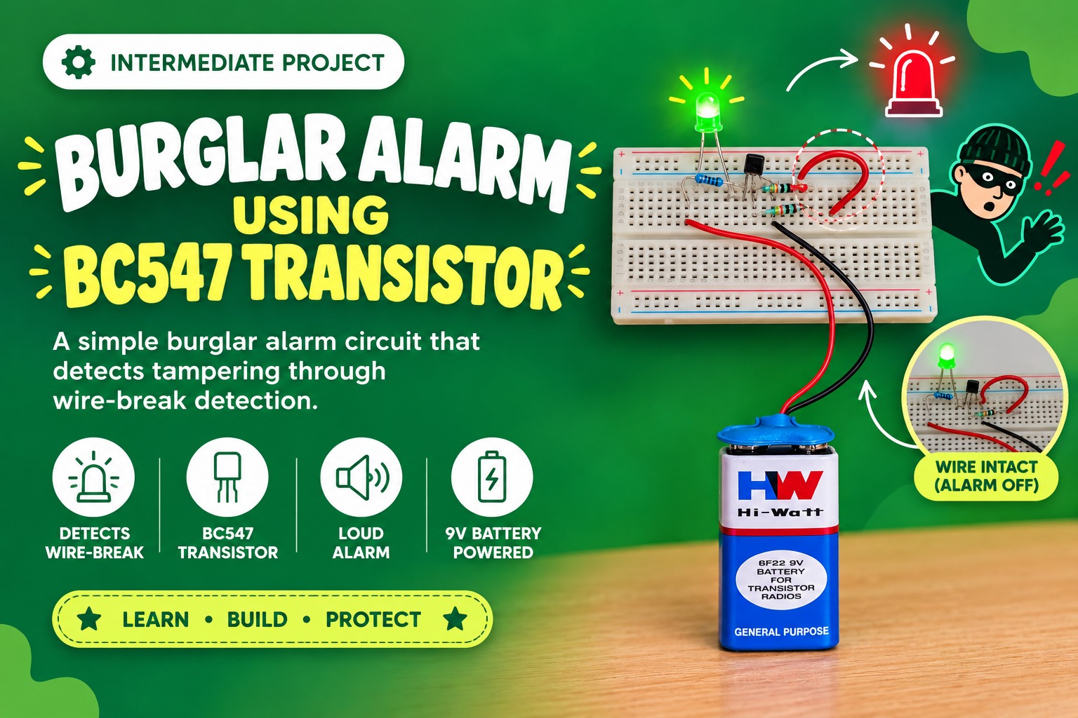
A simple burglar alarm circuit that detects tampering through wire-break detection.
To design a simple burglar alarm circuit that lights up an LED when a wire is cut. This helps students understand how a transistor works as a switch and how basic security circuits detect tampering.
This project demonstrates how a BC547 NPN transistor can be used as a tamper-detect alarm switch.
The alarm works like this:
● When the wire is connected, the transistor stays OFF → LED remains OFF.
● When the wire is cut, the transistor turns ON → LED lights up, indicating intrusion.
➢ Working of BC547 Transistor
➢ Base–emitter control
➢ Using resistors to control current
➢ Making a simple alarm mechanism
➢ Real-life application of security wiring in locks, doors, and safes
1. Breadboard – 1 (for building the circuit)
2. BC547 Transistor – 1 (works as the switch)
3. LED – 1 (acts as an alarm indicator)
4. 100kΩ resistor – 1 (for the base control)
5. 10kΩ resistor – 1 (acts as pull-down for base)
6. Small wire piece – 1 (for alarm loop)
7. Jumper wires – few (for connections)
8. 9V battery – 1 (power supply)
9. Battery connector – 1 (to connect the battery to the circuit)
The BC547 is a general-purpose NPN Bipolar Junction Transistor (BJT). In this circuit, it functions as an electronic switch.
➔ Transistor Type: NPN
➔ Maximum Collector Current (Ic): 100 mA
➔ Maximum Collector-Emitter Voltage (Vce): 45 V
➔ DC Current Gain (hFE): 110 to 800 (varies by specific variant)
➔ Package: TO-92
The transistor acts as a switch for the LED. A small current applied to the Base terminal controls a much larger current flowing through the Collector to the Emitter. When the “trip wire” is intact, the base current is zero, and the transistor is OFF (open switch). When the wire is cut, a base current is established, turning the transistor ON (closed switch), which allows current to power the LED.
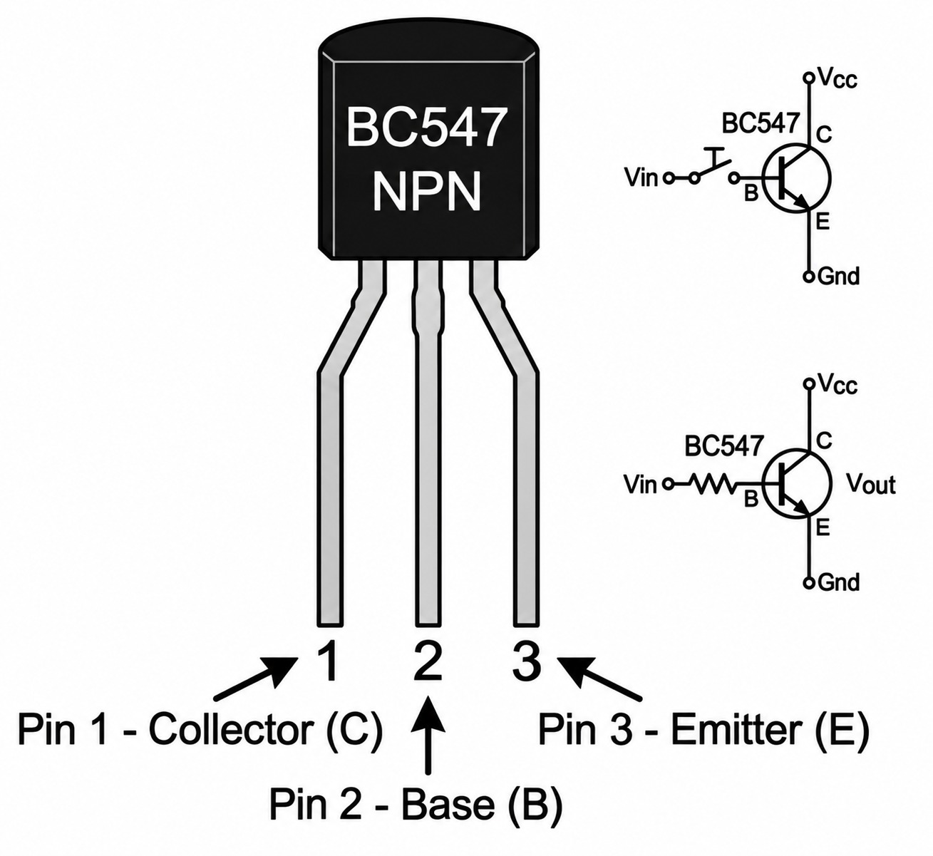
When holding the transistor with the flat side facing you and the pins pointing down, the pins from left to right are: Collector (C), Base (B), Emitter (E).
The burglar alarm is based on wire-break detection.
The wire is connected → base is pulled to ground → transistor OFF → LED OFF.
The wire breaks → base gets biased through the resistor → transistor ON → LED lights up as an alarm.
1. Door security alarms
2. Locker wire-loop alarms
3. Simple DIY tamper sensors
4. Safety signaling systems
● Insert the LED on the breadboard with correct polarity (Anode = longer leg, Cathode = shorter).
➔ If unsure, remember: longer leg = positive.
➔ Use a small buzzer instead of an LED for a sound alarm.
● Place the transistor (TO-92 package) on the breadboard.
● Pin order (flat side facing you): Collector – Base – Emitter
● Connect the collector to the LED’s negative terminal.
➔ Do not bend pins too much; they may break.
➔ You can use a 2N2222 transistor if BC547 is not available.
● Connect 100kΩ between the LED’s positive line and the transistor’s base.
➔ This resistor limits the base current.
➔ You may use 82kΩ–120kΩ if 100kΩ is unavailable.
● Connect the 10kΩ resistor to the pin below the transistor’s base (this creates the security loop connection).
➔ Push the resistor legs firmly so they don’t loosen.
➔ You may use 4.7kΩ–15kΩ depending on sensitivity needed.
● Connect one end of the small wire/jumper wire to the 10kΩ resistor and the other end to the emitter (right pin) of the transistor.
➔ This wire acts as the tamper detection loop.
➔ Use a long wire to extend the loop to a door or window model.
● Battery + → LED’s positive line
● Battery – → Transistor’s emitter
➔ Always connect the negative terminal last for safety.
➔ Use a 3V coin cell + buzzer (without transistor) for mini-version.
● Now test:
1. When the wire is connected → LED OFF
2. Cut or remove the wire → LED turns ON (alarm triggered)
➔ You can simulate cutting by simply pulling the wire out.
➔ Attach foil to a door; when the door opens, the foil breaks → alarm triggers.
● LED not turning ON even after cutting the wire:
➔ Check battery voltage (should be above 7V).
➔ Ensure the LED polarity is correct (long leg = +).
➔ Verify transistor orientation (flat side facing you).
➔ Ensure the 100kΩ resistor is properly connected from LED line to base.
● LED glowing even when wire is connected:
➔ The wire loop is loose or not fully touching.
➔ Poor connection between resistor and base.
➔ Replace the 10kΩ resistor if damaged.

Wire shorts the transistor’s base to ground → Base-emitter voltage = low → transistor OFF → LED OFF.
Wire is cut → base receives voltage through 100kΩ resistor → Base-emitter voltage increases → BC547 conducts → LED glows as alarm.
This simple mechanism is used in many basic security circuits.
★ Wire connected: LED remains OFF
★ Wire cut/disconnected: LED turns ON
A fully working burglar alarm circuit that detects tampering using a transistor switch.


➔ Do not connect the 9V battery directly to the LED without resistors.
➔ Avoid bending or pulling the transistor pins too hard—they may break.
➔ Make sure there are no loose wires, as they can cause incorrect triggering.
➔ Add a buzzer to make it a sound alarm.
➔ Add a switch to turn the alarm ON/OFF.
➔ Add a laser + LDR to convert it into a laser tripwire alarm.
➔ Convert it into a door alarm by placing the wire on the door frame.
IGNITING THE PASSION FOR ROBOTICS IN KIDS.