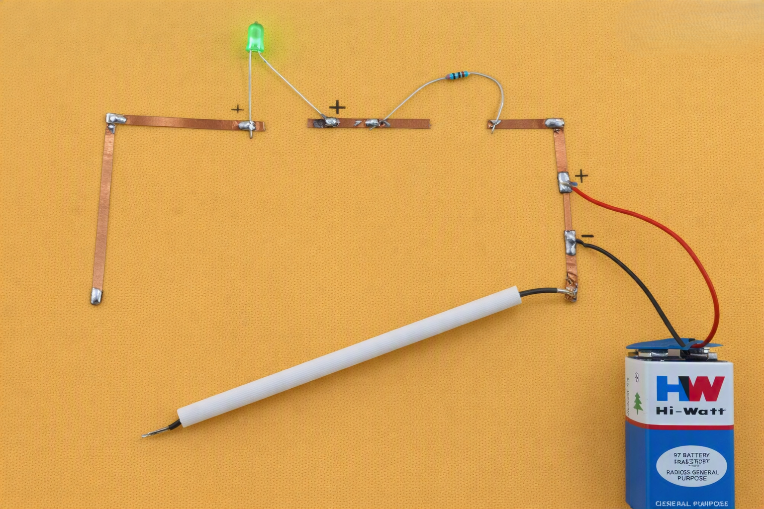
DIY BEGINNER PROJECT NO.04 (TILT-TO-GLOW CIRCUIT)

Tilt to Glow Circuit | Project Repository
PROJECT REPOSITORY

Tilt to Glow Circuit

Design and build a simple LED circuit using a 9V battery, resistor, LED, and a tilt-based switching mechanism on a copper strip board or copper tape circuit. The LED lights up when the base is tilted at a specific angle.

Note: Please read the full instructions before making the product.

Category

DIY Electronics Project

Level

Beginner

TABLE OF CONTENTS

AIM

To design and build a simple LED circuit using a 9V battery, resistor, LED, and a tilt-based switching mechanism on a copper strip board or copper tape circuit that lights up when the base is tilted at a specific angle.

OBJECTIVE

This project demonstrates how an electrical circuit can be controlled using a physical tilt switch. The tilt motion completes the circuit, allowing the LED to glow and showing how sensors or switches can control current flow in simple systems.

MATERIALS REQUIRED

Material Quantity
LED 1
9V Battery 1
Battery Connector 1
Resistor – preferably 1kΩ 1
Copper Strip Board or Copper Tape Small pieces
Speaker Wires 2–3 pieces
Straw – acts as a simple tilt switch 1
Cardboard / Thermocol / Foam Board 1 (A5 or A4 size)
Insulation Tape or Glue As needed
White Paper 1 sheet
Colors or Markers For circuit layout and labeling

CIRCUIT DESIGN CONCEPT

★ The tilt mechanism acts as a manual switch for the power supply.

★ When the setup is tilted, a wire inside a straw rolls to one end and touches a copper path connected to the battery’s positive terminal.

★ This action completes the circuit by delivering power to the LED and resistor, causing the LED to light up.

★ This demonstrates how a position-based switch can control a circuit.

This demonstrates:

  • Flow of electric current
  • Position-based switching
  • Open and closed circuit behaviour
  • Electrical energy conversion into light energy
  • How physical movement can control a circuit

PROCEDURE

Follow the steps below carefully to assemble the Tilt to Glow Circuit.
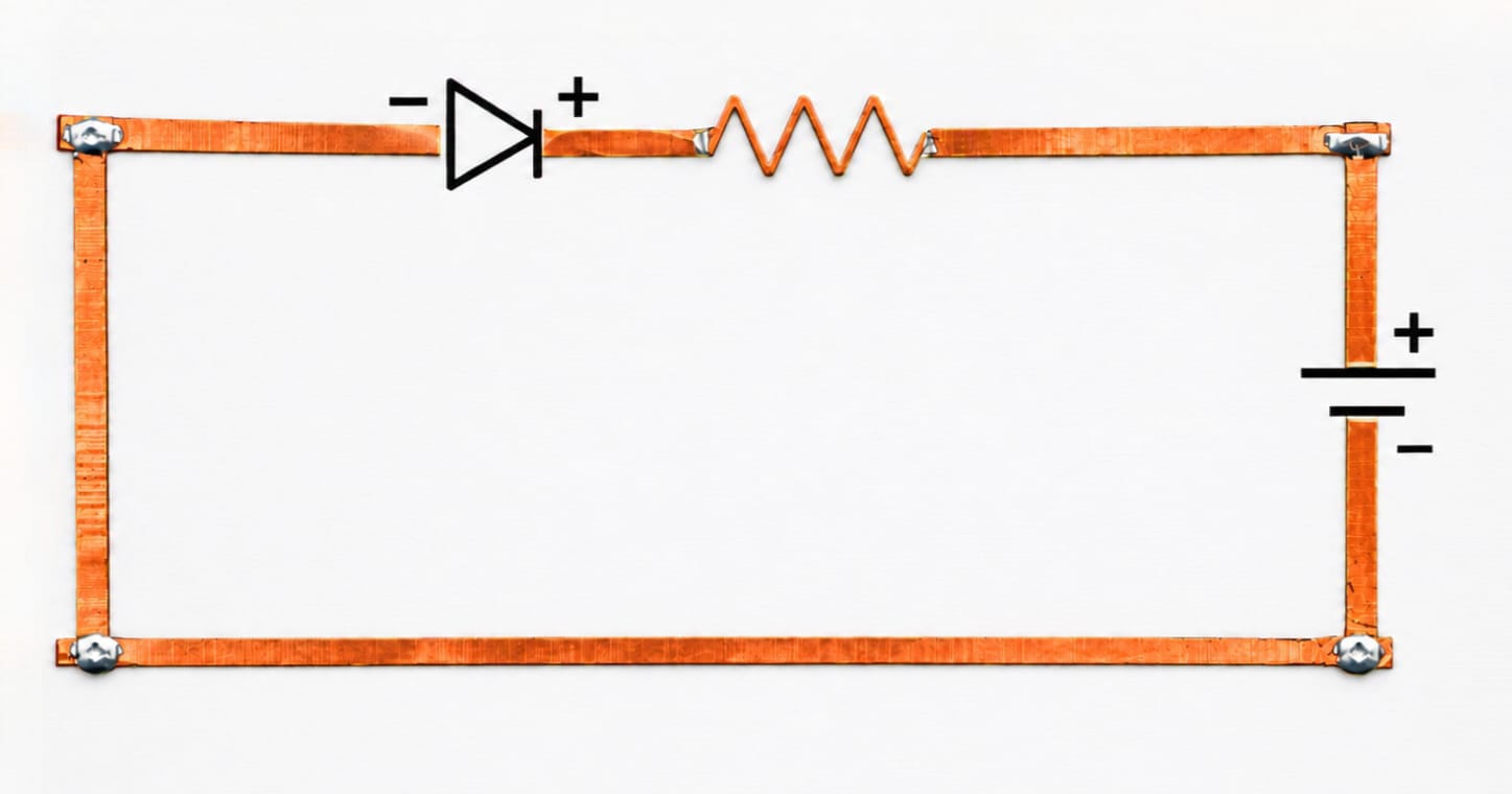
STEP 1

PREPARE THE BASE

  • Cut a piece of cardboard or thermocol in A5 or A4 size.
  • Stick a white sheet on top of the base.
  • Draw the layout of the circuit clearly.
  • Stick copper strips or copper tape along the drawn paths to act as conductors.

💡 ALTERNATIVES & TIPS

  • Instead of copper tape, you can use aluminum foil or conductive paint.
  • Ensure the positive and negative copper paths do not touch to prevent short circuits.
  • Label the components and paths clearly for easy understanding.

Step 1. Prepare the Base

STEP 2

INSERT AND FIX THE LED

  • Insert the LED into the base.
  • The longer leg is the anode (+), and the shorter leg is the cathode (–).
  • Fix the LED legs onto their respective copper paths.
  • Connect the Anode (+, long leg) to the central copper path.
  • Connect the Cathode (–, short leg) to the copper path that leads directly to the battery’s negative terminal (black wire).

💡 ALTERNATIVES & TIPS

  • If the LED does not stay upright, make small holes to insert the legs.
  • You can also use a small amount of glue to stabilize the LED.
  • Always check the LED polarity before connecting the battery.

Step 2. Insert and Fix the LED

STEP 3

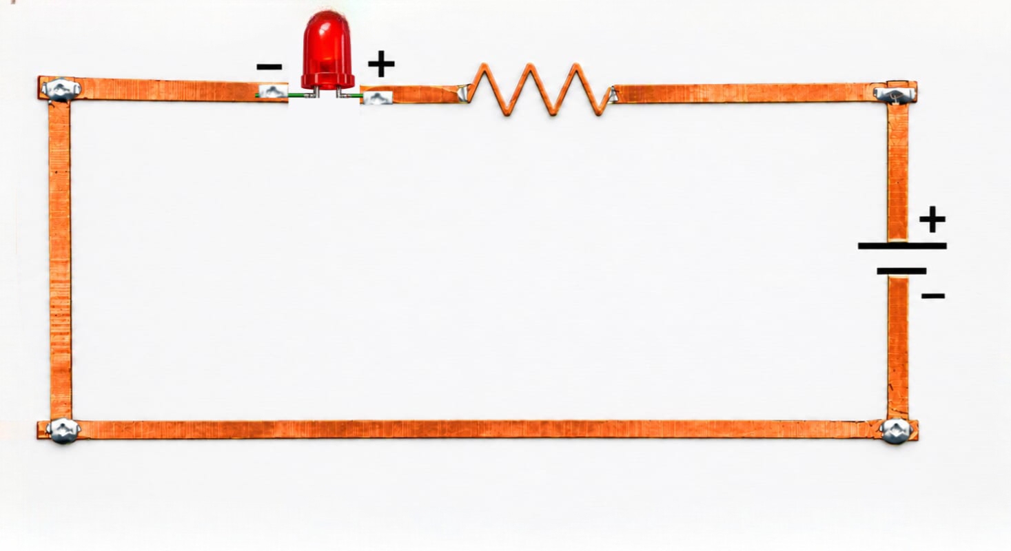
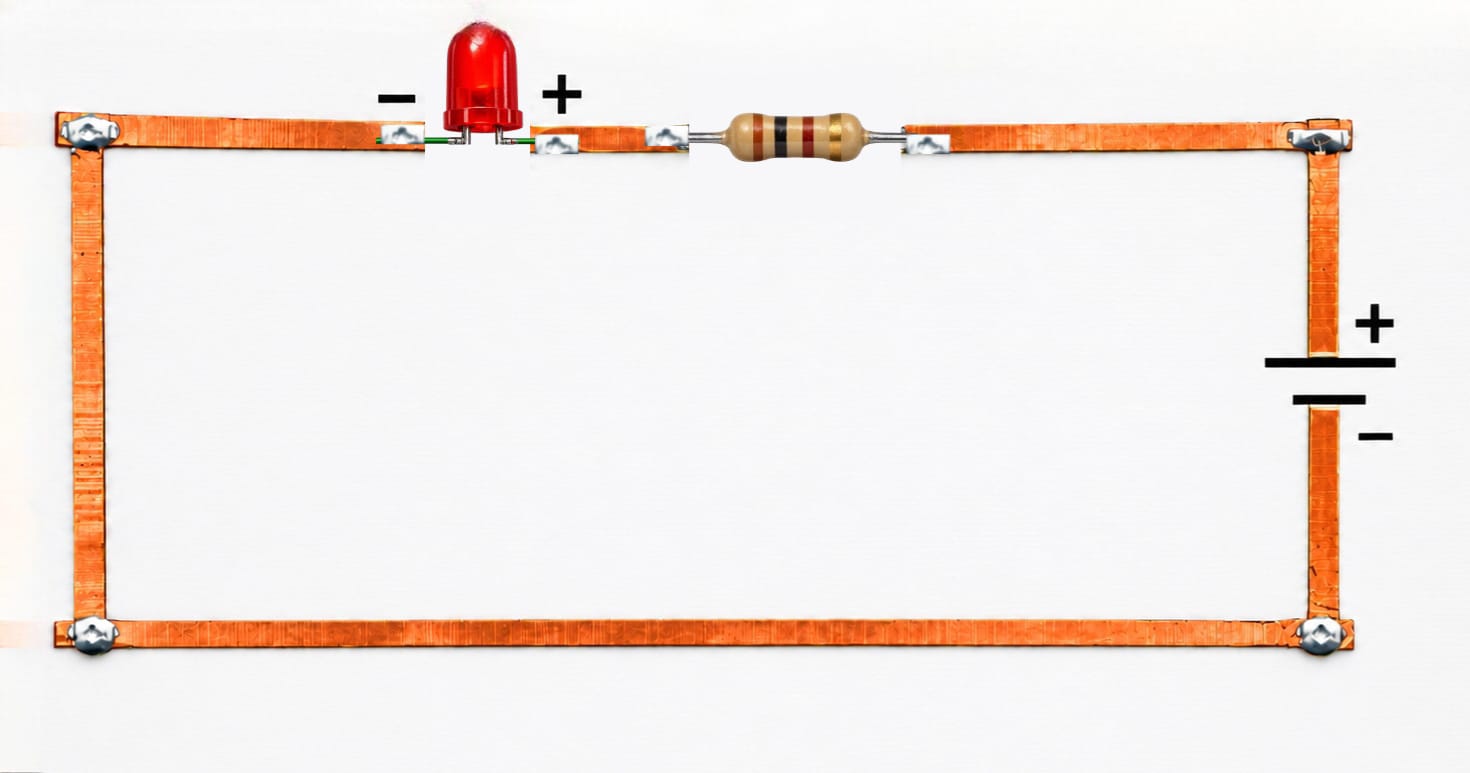
CONNECT THE RESISTOR

  • Connect one end of the resistor to the same central copper path as the LED’s anode.
  • Connect the other end of the resistor to the copper path designated for the tilt switch connection.
  • This path will be activated by the tilt mechanism to receive power.

💡 ALTERNATIVES & TIPS

  • A resistor in the 470Ω–1kΩ range works well with a 9V battery.
  • The resistor is essential to limit current and protect the LED.

Step 3. Connect the Resistor

STEP 4

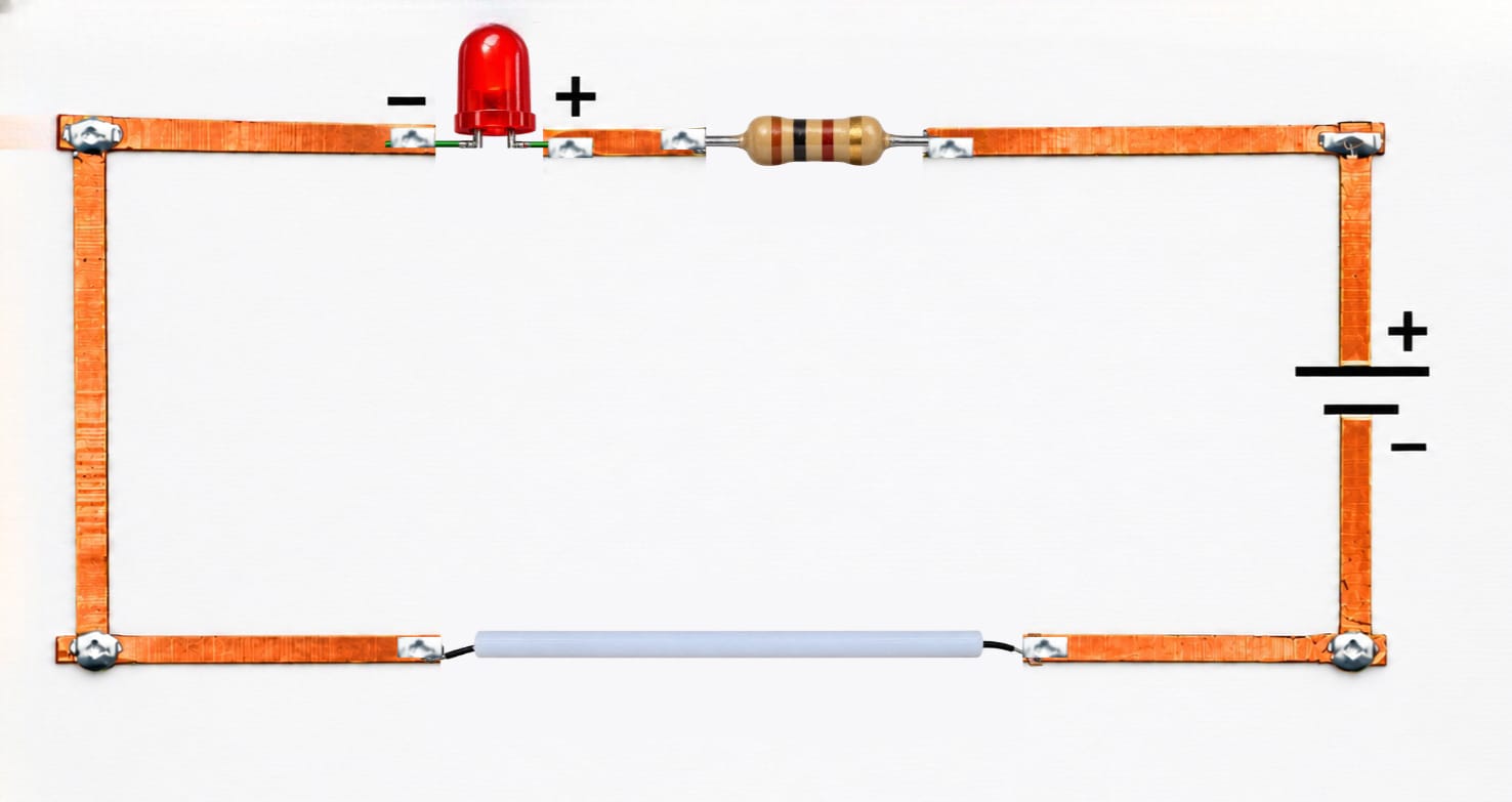
MAKE THE TILT SWITCH – THE POWER GATE

  • Take a plastic straw and insert a short piece of thin, bare copper wire loosely inside it.
  • Securely connect one end of a separate fixed wire to the copper path that leads to the resistor.
  • This is the “Tilt Switch Connection” path.
  • Tape the other end of this wire to the inside of one end of the straw.
  • This allows the loose wire inside the straw to make contact when the setup is tilted.
  • Fix the straw to the board at an angle.
  • When tilted, the loose wire inside rolls and bridges the connection between the fixed wire and the copper path connected to the battery’s positive terminal.

💡 ALTERNATIVES & TIPS

  • For better contact, you can solder the fixed wire to a small piece of foil inside the straw.
  • A small metal ball bearing can be used instead of a wire for more sensitive tilt detection.
  • Ensure the tilting motion is smooth and the connection is clear.

Step 4. Make the Tilt Switch – The Power Gate
STEP 5

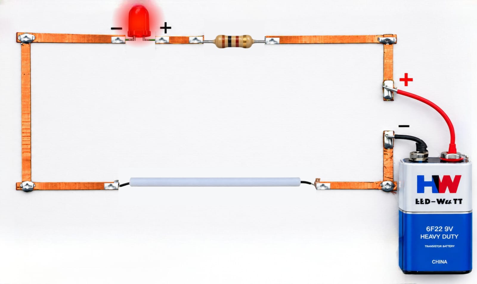
BATTERY CONNECTIONS

  • Connect the battery connector wires.
  • Connect the red wire (positive) to the copper path that runs alongside the straw – the “Battery +” path.
  • Connect the black wire (negative) directly to the copper path connected to the LED’s cathode.

💡 ALTERNATIVES & TIPS

  • If you do not have a battery clip, you can carefully tape wires directly to the 9V battery terminals.
  • Always double-check the polarity before finalizing the connections.

Step 5. Connect the Battery

STEP 6

TEST THE CIRCUIT

  • Attach the 9V battery.
  • Keep the setup flat. The LED should not glow because the circuit is open.
  • Tilt the board toward the straw switch.
  • When the loose wire inside touches both the fixed straw wire and the positive battery path, the circuit closes and the LED glows.

💡 TROUBLESHOOTING TIPS

  • If the LED does not glow, check all connections for continuity.
  • Ensure the LED is not inserted backwards.
  • Verify that the resistor is properly connected and functional.
  • Clean the copper paths to ensure there are no insulating residues.

Step 6. Test the Tilt to Glow Circuit
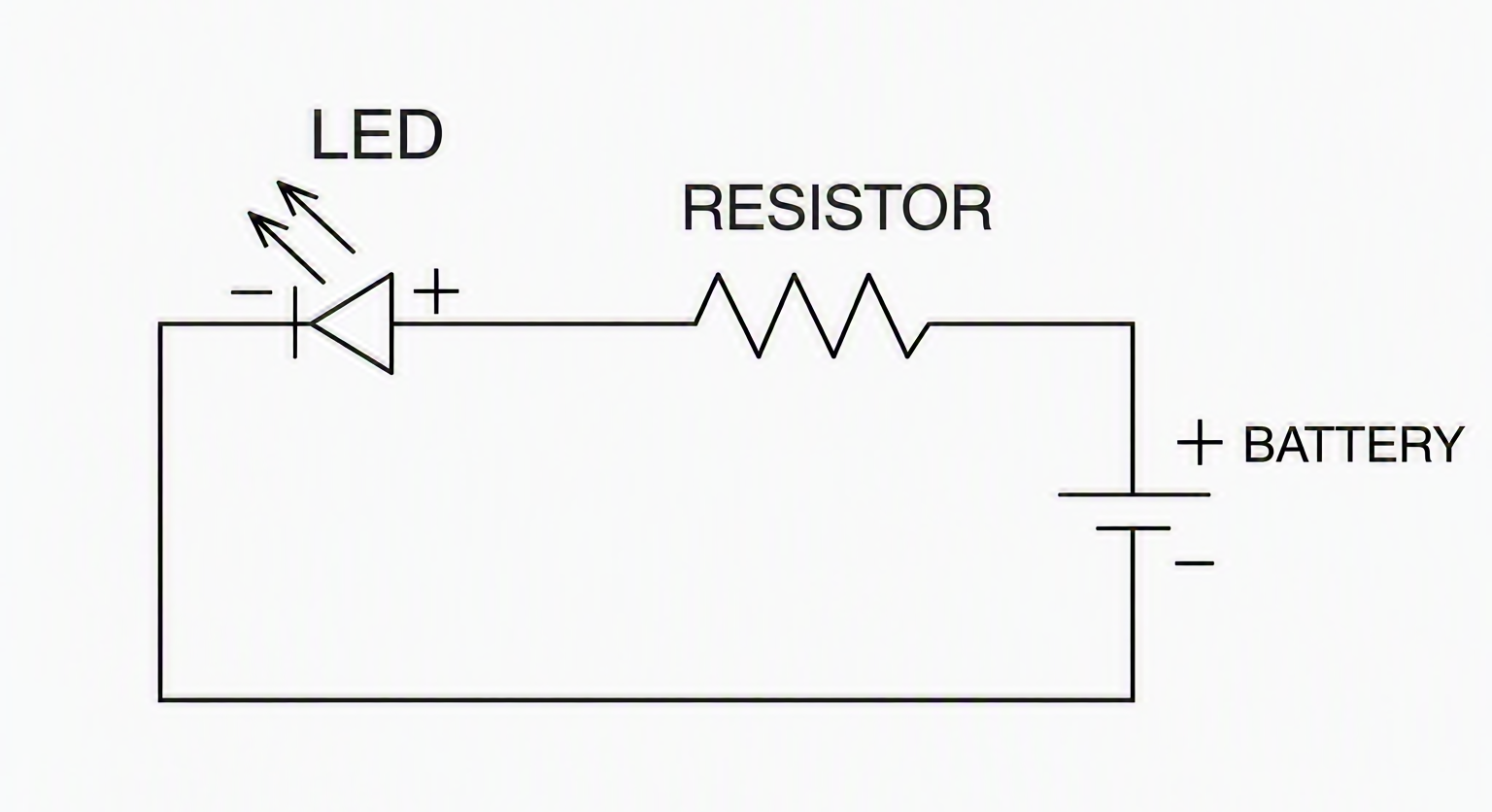
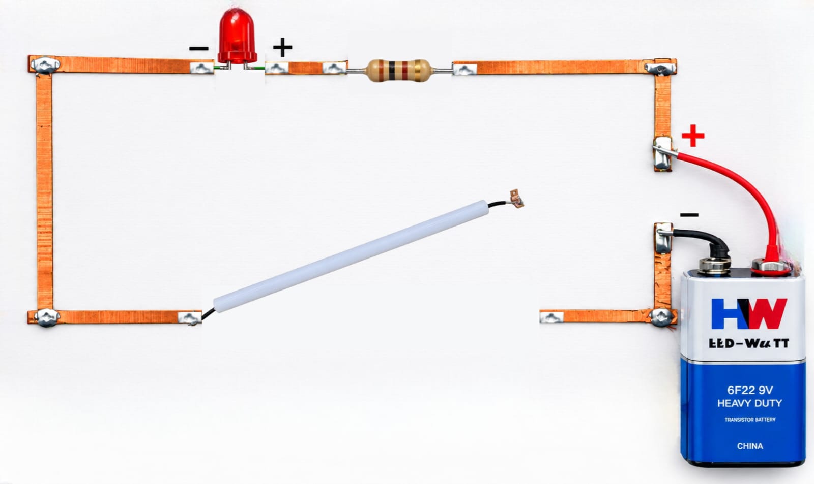
CIRCUIT DIAGRAM

Figure 1. Circuit Diagram of the Tilt to Glow Circuit

WORKING PRINCIPLE

When the base is tilted, the loose wire inside the straw rolls and makes contact, closing the circuit. This allows current to flow from the battery’s positive terminal, through the tilt switch, through the resistor, through the LED, and back to the battery’s negative terminal. The LED converts this electrical energy into light. When the tilt is reversed, the connection is broken, the circuit opens, and the LED turns off. This demonstrates a simple yet effective tilt-activated switch.

FINAL RESULT

A fully functional Tilt to Glow LED Circuit was successfully built using copper strips and a handmade tilt switch. The LED lights up only when the system is tilted at a specific angle, confirming the creation of a position-sensitive electrical switch.

SAMPLE OUTPUT

(i) Without tilting → Open Circuit

Sample Output – Without Tilting / Open Circuit


(ii) With tilting → Closed Circuit
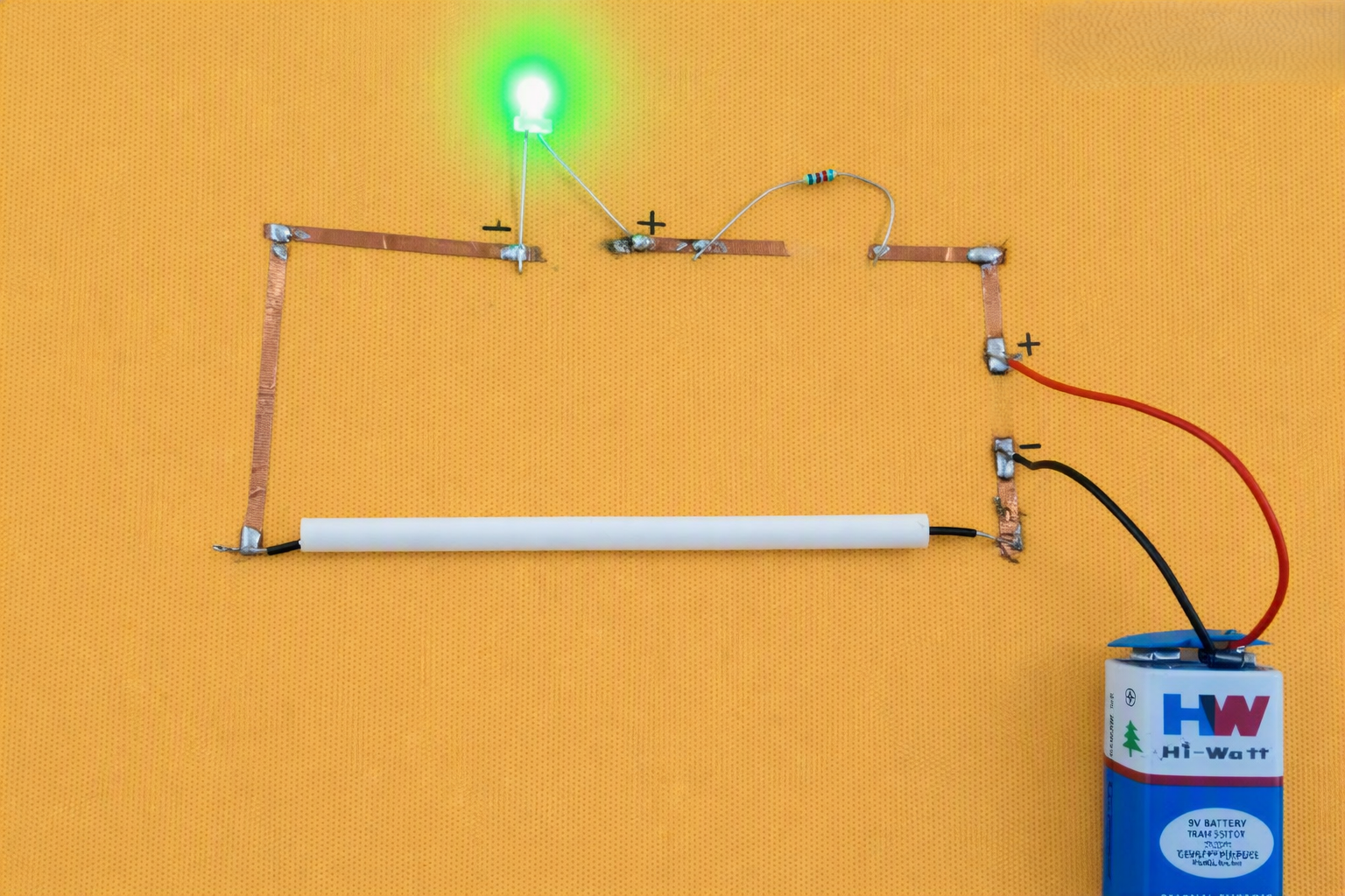
Sample Output – With Tilting / Closed Circuit

ADDITIONAL NOTES

  • Always test the complete circuit before permanently fixing all components.
  • Make sure the copper paths are clean and properly connected.
  • Ensure the positive and negative paths do not touch each other.
  • Check the LED polarity and resistor connections before testing.
  • Keep the tilt mechanism free to move so that the wire can roll smoothly.

SAFETY

  • Always disconnect the battery when the circuit is not in use to prevent overheating or leakage.
  • Handle scissors, cutters, and wires carefully.
  • Be careful while working with bare copper wire.
  • Ensure there are no accidental short circuits between the positive and negative paths.

CREATIVITY EXTENSION

  • Convert it into a game circuit, such as a balance board that lights up when leveled.
  • Add multiple LEDs for multi-angle indicators.
  • Use different resistor values for brightness control.
  • Decorate the base with creative designs and labels.
  • Experiment with different tilt angles to change when the LED turns ON.

Leave A Comment

Your email address will not be published. Required fields are marked *