DIY BEGINNER PROJECT NO.07 (VOTING SYSTEM – LIGHT UP YOUR VOTE !)

Voting System | Project Repository
PROJECT REPOSITORY

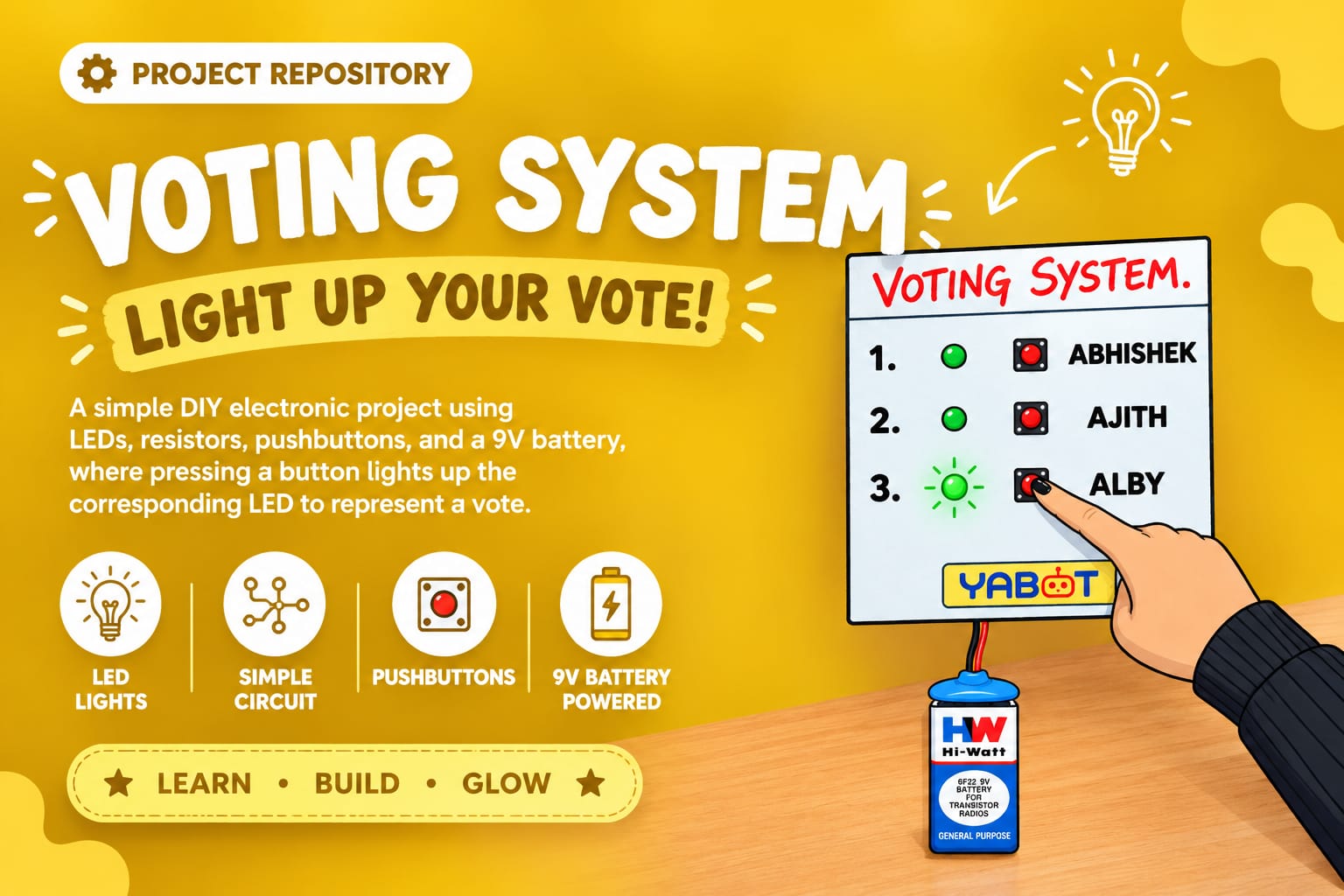
Voting System – Light Up Your Vote!

Design and build a simple Voting System model using LEDs, resistors, pushbuttons, and a 9V battery, where pressing a button lights up the corresponding LED to represent a vote.

Note: Please read the full instructions before making the product.

Category

DIY Electronics Project

Level

Beginner

TABLE OF CONTENTS

AIM

To design and build a simple Voting System model using LEDs, resistors, pushbuttons, and a 9V battery, where pressing a button lights up the corresponding LED to represent a vote.

OBJECTIVE

This project introduces students to the basics of switch-controlled circuits, LED polarity, and parallel connections using a fun voting activity. Each button represents a candidate or option, and the LED glows only when the button is pressed—simulating a voting machine.

The project enhances understanding of:

  • Current flow
  • Role of resistors
  • Switch operation
  • Practical wiring on cardboard
  • Creativity in making functional mini-projects

MATERIALS REQUIRED

Material Quantity
LEDs 3
Resistors 3
Pushbuttons 3
9V Battery 1
Battery Connector 1
Insulation Tape As Needed
Glue / Fevicol / Glue Gun As Needed
Paper or Cardboard For base
Scissors / Cutter 1
Colours / Sketch Pens For decoration
Base / Stand Cardboard or Thermocol

CIRCUIT DESIGN CONCEPT

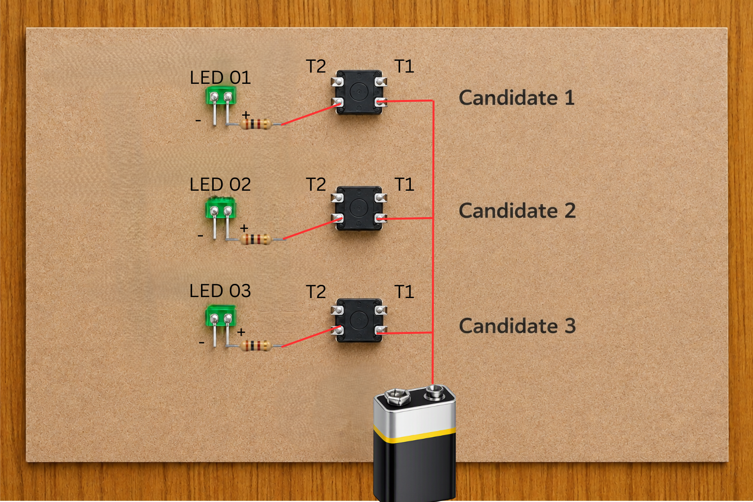
  • Each LED and button forms a separate branch in a parallel circuit.
  • The positive terminal of the battery connects to one side of all pushbuttons.
  • The other side of each pushbutton connects to the LED through a resistor.
  • The negative terminal of all LEDs merge into a common ground and return to the battery (–).
  • When a pushbutton is pressed:

Battery (+) → Button → Resistor → LED → Battery (–)

This allows only the selected LED to glow.

PROCEDURE

Follow the steps below carefully to assemble the Voting System.

STEP 1

PREPARE THE BASE

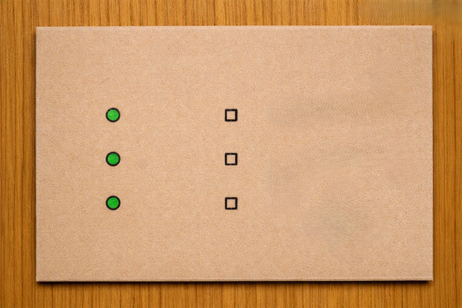
  • Take a cardboard sheet.
  • Mark 3 LED positions in a row.
  • Mark pushbuttons beside each LED, either on the right side or left side.

Example layout:

  • [LED 1] [Button 1]
  • [LED 2] [Button 2]
  • [LED 3] [Button 3]

💡 TIP

  • Keep at least 2–3 cm gap for clean wiring.

🔄 ALTERNATIVE

  • Use thick thermocol if you want a neater, raised design.

Step 1. Prepare the Base

STEP 2

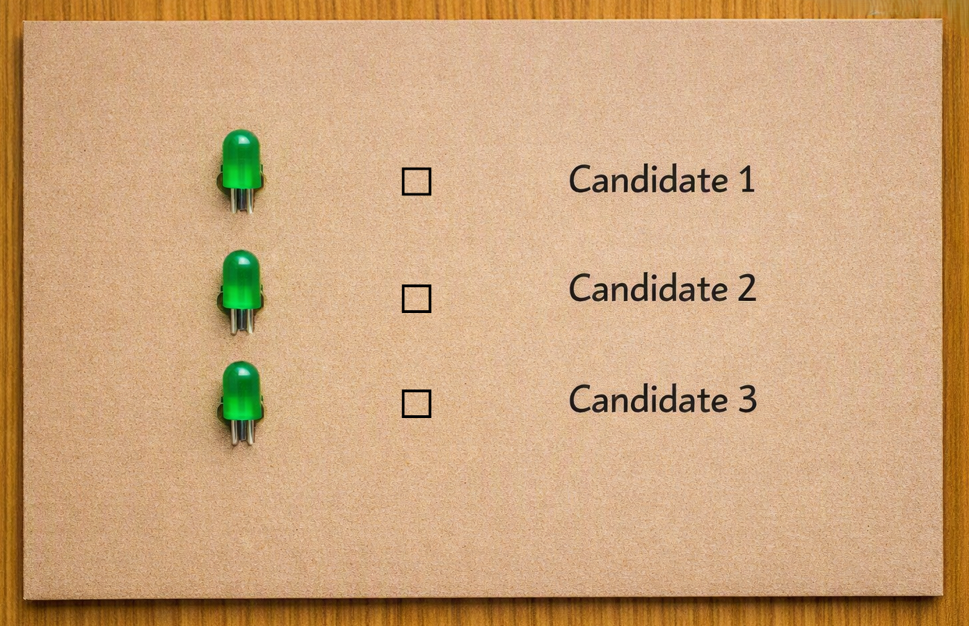
FIX THE LEDs ON THE BOARD

  • Insert each LED into the cardboard.
  • Label them as Candidate 1.
  • Label them as Candidate 2.
  • Label them as Candidate 3.

💡 TIP

  • Identify polarity before fixing.
  • Long leg = Anode (+).
  • Short leg = Cathode (–).

🔄 ALTERNATIVE

  • If the hole becomes big, tape around the LED base.

Step 2. Fix the LEDs on the Board

STEP 3

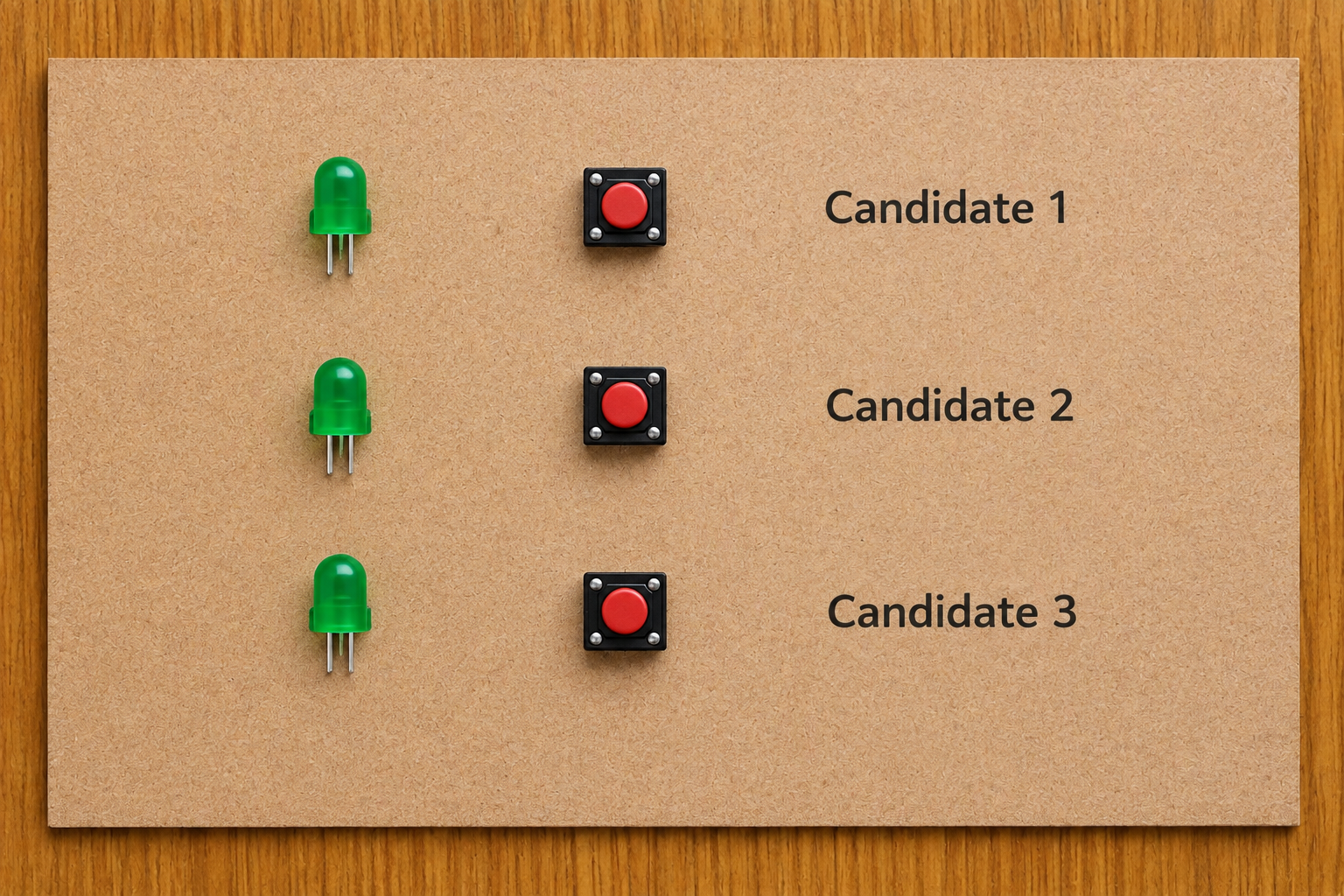
MOUNT THE PUSHBUTTONS BESIDE THE LEDs

  • Fix each pushbutton next to its corresponding LED.
  • Glue them so they do not move.

💡 TIP

  • Make sure all buttons face the same direction for easy wiring.

🔄 ALTERNATIVE

  • Use small tactile switches if pushbuttons are unavailable.

Step 3. Mount the Pushbuttons Beside the LEDs
STEP 4

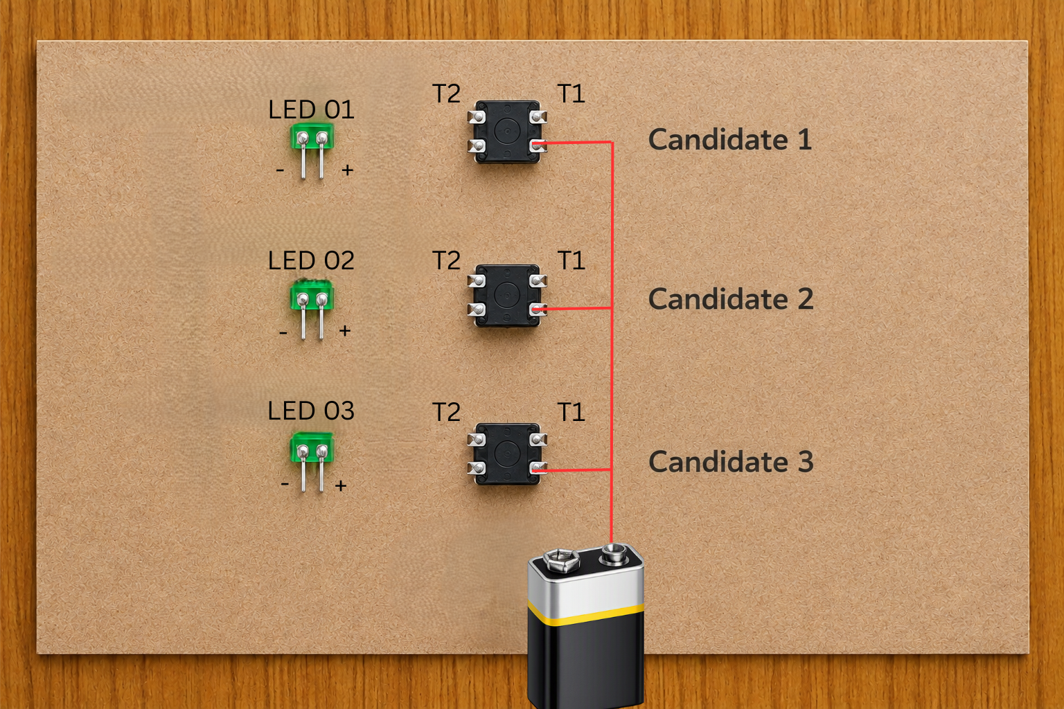
CONNECT THE POSITIVE SIDE

  • Take a single red wire and connect the first terminal of all pushbuttons.
  • Join this wire to the battery’s + (positive) terminal.
  • This acts as the common positive rail.

💡 TIP

  • Use one long red wire to keep the positive line clean.

🔄 ALTERNATIVE

  • Use short connected wire sections if a single long wire is not available.

Step 4. Connect the Positive Side

STEP 5

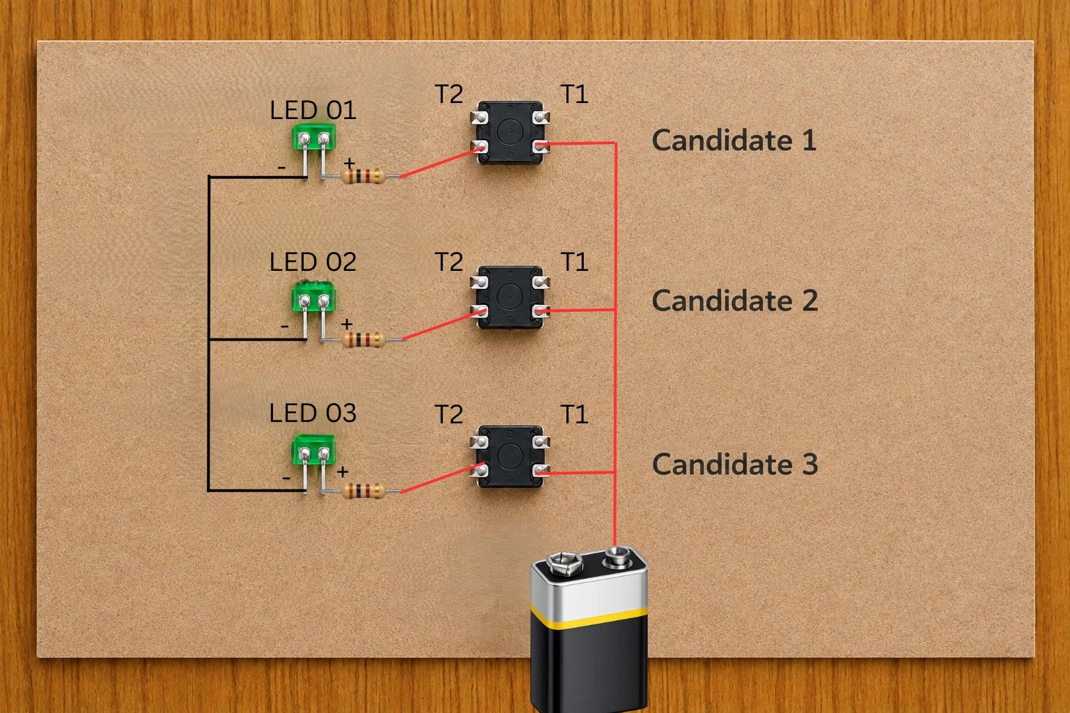
CONNECT EACH BUTTON TO ITS LED

  • From the free terminal of each pushbutton, connect a resistor.
  • Connect the other end of the resistor to the anode (+) of its LED.
  • This completes the individual branch connection.

💡 TIP

  • Keep the resistor and wires arranged neatly so that each button can be easily traced to its corresponding LED.

🔄 ALTERNATIVE

  • A resistor between 470Ω and 1kΩ can be used depending on the LED and battery arrangement.

Step 5. Connect Each Button to Its LED
STEP 6

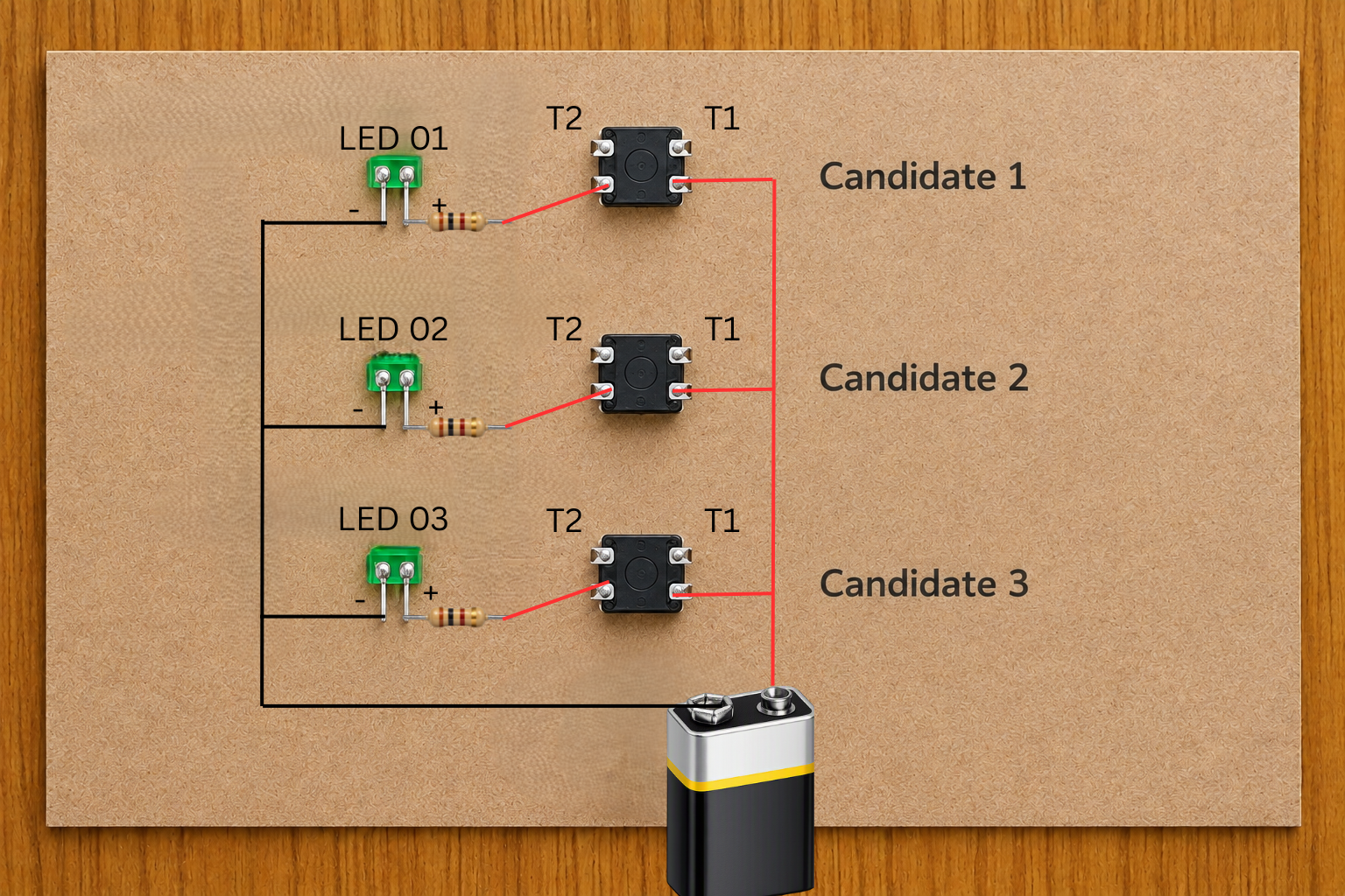
CONNECT ALL LED NEGATIVE TERMINALS

  • Join all cathodes (–) of the LEDs together.
  • Connect this common point to the battery – (negative) wire.
  • This forms the ground line.

💡 TIP

  • Use one common black wire as the ground line.

🔄 ALTERNATIVE

  • If the wires are short, extend them using additional insulated wire pieces.

Step 6. Connect All LED Negative Terminals
STEP 7

ATTACH THE BATTERY

  • Connect your battery connector to the 9V battery.
  • Check that all connections are tight.

💡 TIP

  • Tape the battery on the side or behind the board for a cleaner look.

🔄 ALTERNATIVE

  • Create a small battery pocket using cardboard to hold the battery securely.

Step 7. Attach the Battery

STEP 8

TESTING THE VOTING SYSTEM

  • Press the buttons beside each LED.
  • Press Button 1 → LED 1 must glow.
  • Press Button 2 → LED 2 must glow.
  • Press Button 3 → LED 3 must glow.

If an LED does not glow, check:

  • LED polarity.
  • Loose connections.
  • Resistor placement.
  • Battery connection.
  • Pushbutton connections.

💡 TIP

  • Test each button individually to identify the correct LED branch.
  • Make sure the battery connector is firmly attached.

🔄 ALTERNATIVE

  • Different LED colours can be used to represent different candidates.

Step 8. Testing the Voting System

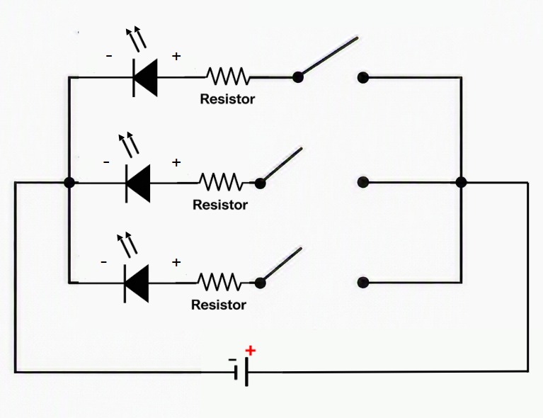
CIRCUIT DIAGRAM

Figure 1. Circuit Diagram of the Voting System

WORKING PRINCIPLE

When a pushbutton is pressed, it completes the circuit for its specific branch.

Current flows through:

Battery (+) → Pushbutton → Resistor → LED → Battery (–)

The LED glows only during pressing—indicating a vote.

This teaches:

  • Switch operation
  • Parallel circuits
  • Controlled current flow
  • Real-world voting machine concept

FINAL RESULT

A functional Voting System Board is created where each candidate has a dedicated button and LED. Pressing a button lights that LED, showing a “vote” has been cast. Kids can count votes by noting how many times each LED glows.

SAMPLE OUTPUT

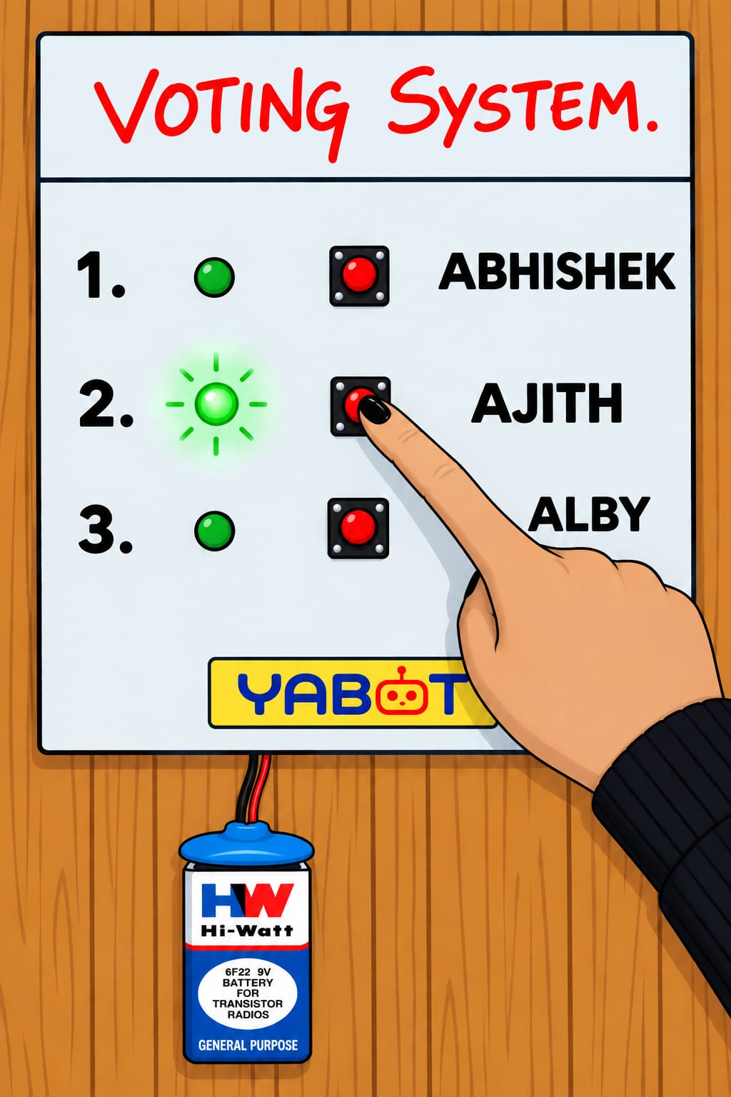
(i) LED OFF – No vote

All buttons released → No LED glowing.
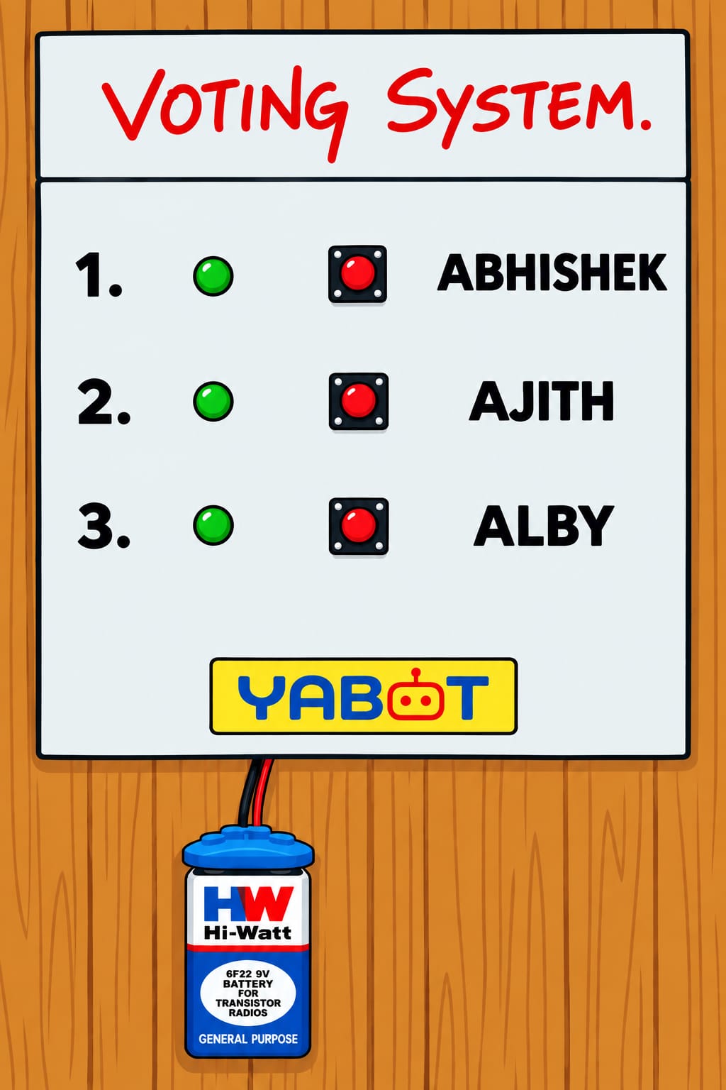
Sample Output – LED OFF / No Vote


(ii) LED ON – Vote registered

When a button is pressed → Corresponding LED lights up.
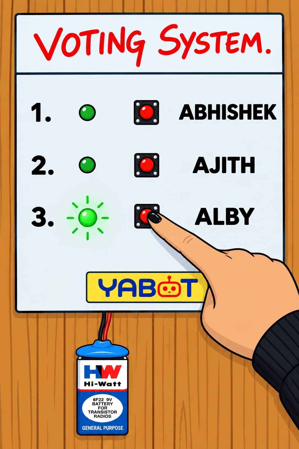
Sample Output – LED ON / Vote Registered

🎥 MAKER’S LAB VIDEO

Watch the Maker’s Lab video to understand the Voting System project and its working.

▶️ Watch the Voting System Project Video

ADDITIONAL NOTES

  • Test the complete circuit before using the Voting System.
  • Always disconnect the battery when the project is not in use.
  • Make sure all wire connections are secure and properly insulated.
  • Keep the pushbuttons firmly fixed to the board.
  • Keep the battery accessible for easy removal or replacement.

SAFETY

  • Always disconnect the battery when not in use.
  • Tape all wire joints to avoid short circuits.
  • Avoid touching bare wires while pressing the buttons.
  • Keep pushbuttons glued strongly so they don’t pop out.
  • Handle scissors and cutters carefully.
  • Use a glue gun under proper supervision.

CREATIVITY EXTENSION

  • Add a decorated title like “VOTING SYSTEM”.
  • Write candidate names creatively.
  • Add borders, stickers, or coloured themes.
  • Use colored markers to match each LED.
  • Create a scoreboard area to note vote counts.
  • Design it like a mini EVM (Electronic Voting Machine).

Leave A Comment

Your email address will not be published. Required fields are marked *