RADAR stands for Radio Detection and Ranging. It’s a technology that detects the presence, distance, and sometimes speed of objects by sending out a signal (traditionally radio waves) and measuring how long it takes for that signal to bounce off an object and return.
The basic principle is simple:
This project uses the same core principle, but with ultrasonic sound waves instead of radio waves — technically this makes it a SONAR-style system (Sound Navigation And Ranging), though it mimics a radar’s sweeping display and behaviour. The physics of “send a wave, time the echo, calculate distance” is identical.
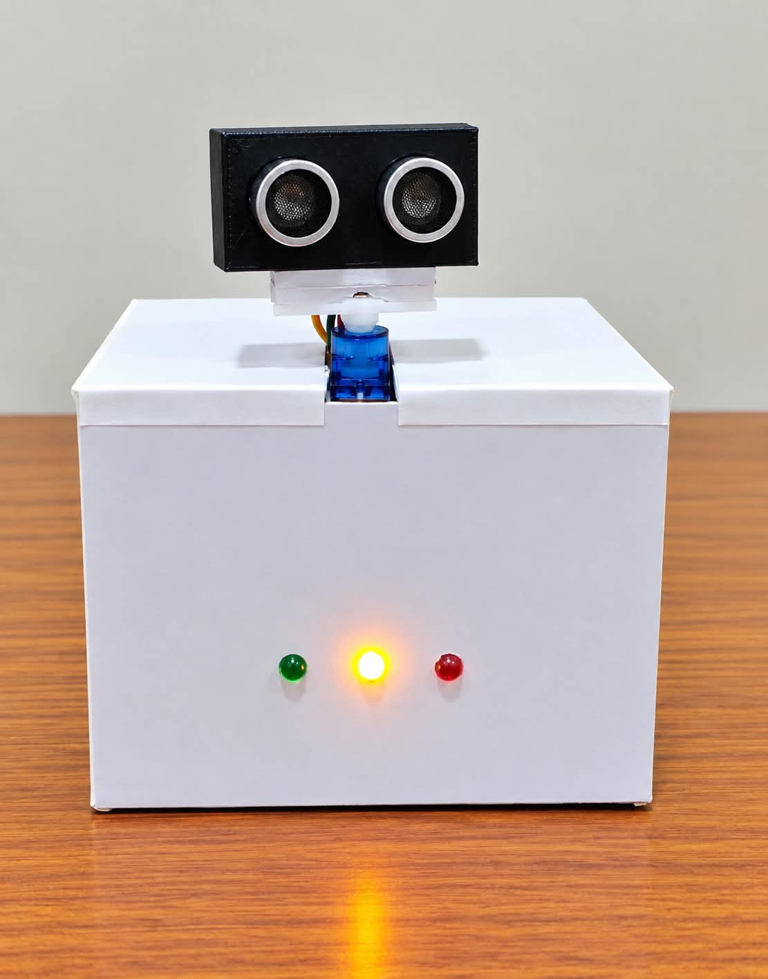
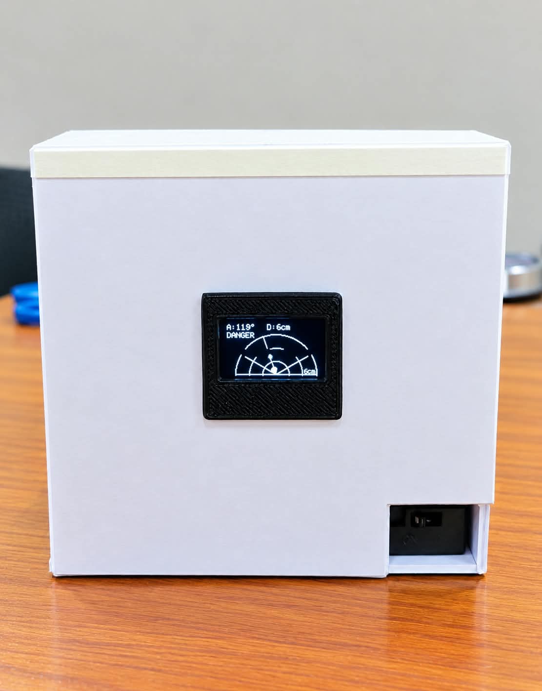
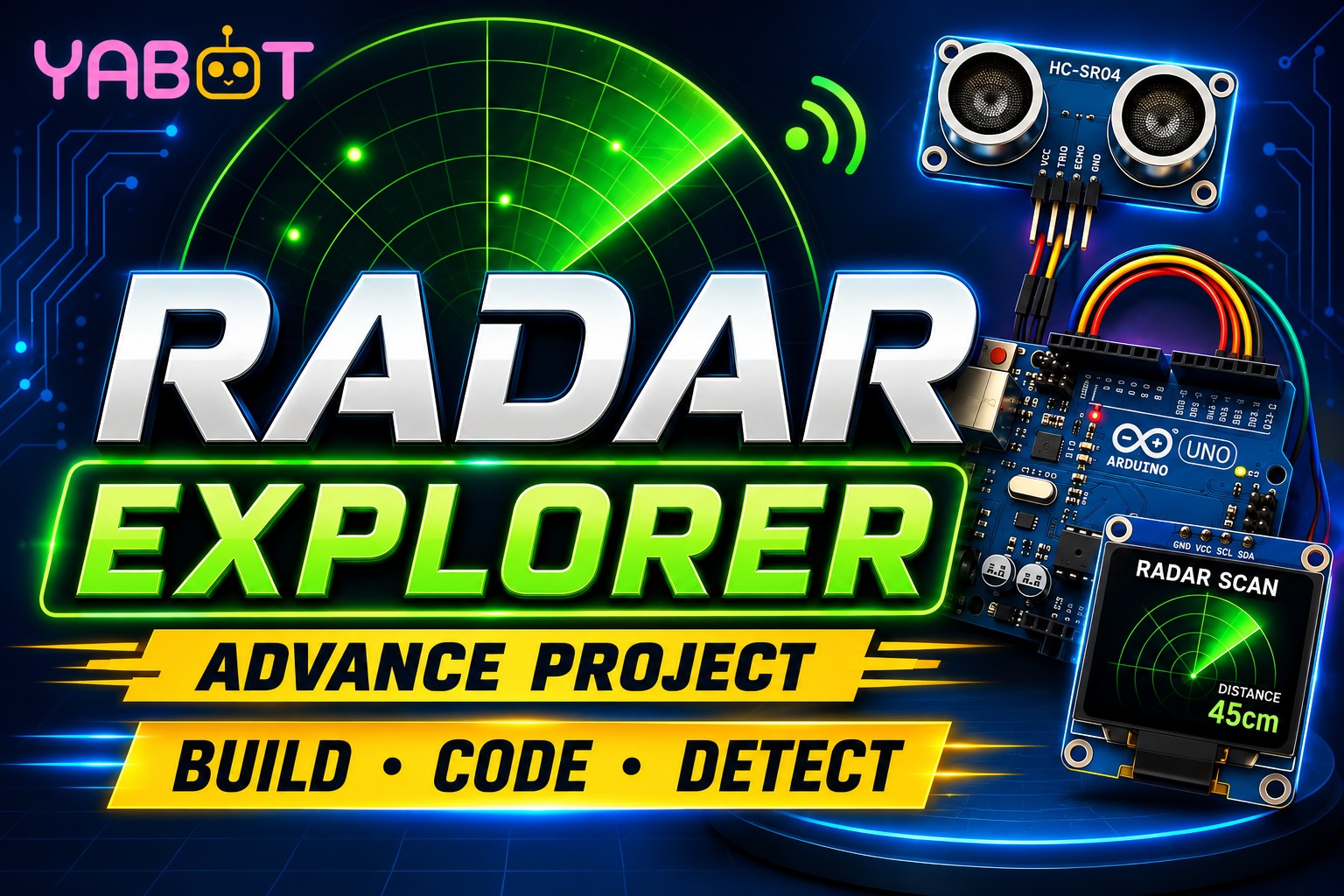
This is an Arduino-based radar system. An ultrasonic sensor mounted on a servo motor sweeps back and forth like a real radar, measuring the distance to nearby objects. The results are shown live on an OLED screen as a radar-style display, while LEDs and a buzzer warn you when something gets too close.
| Component | Quantity | Purpose |
|---|---|---|
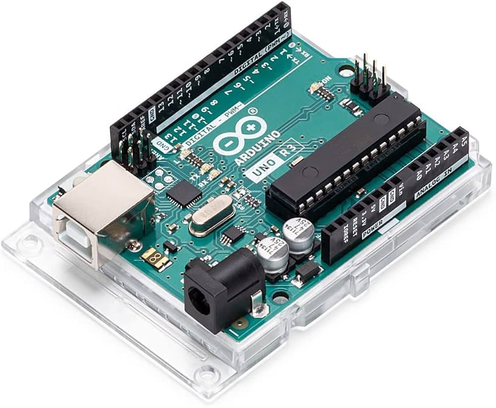
| Arduino (Uno or similar) | 1 | Main controller / brain |
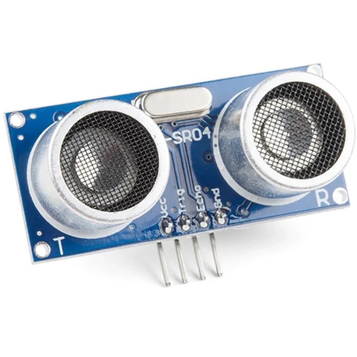
| HC-SR04 Ultrasonic Sensor | 1 | Measures distance using sound waves |
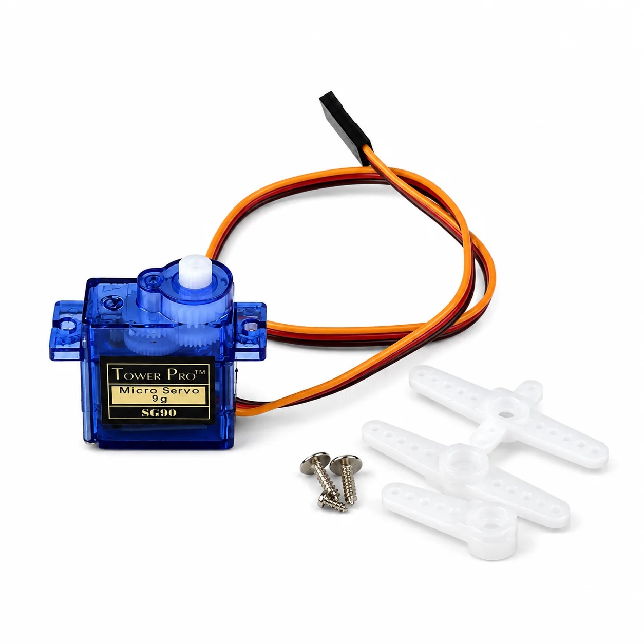
| SG90 Servo Motor | 1 | Rotates the sensor to scan side to side |
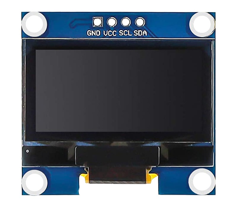
| SSD1306 OLED Display (0.96″, I²C) | 1 | Shows the radar screen |
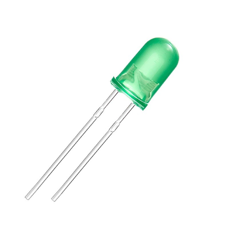
| Green LED | 1 | Indicates “Safe” zone |
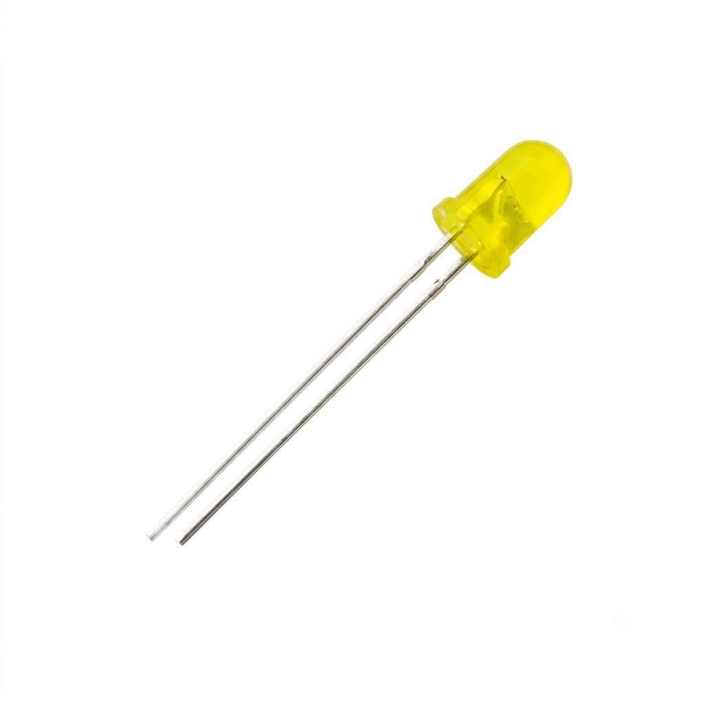
| Yellow LED | 1 | Indicates “Warning” zone |
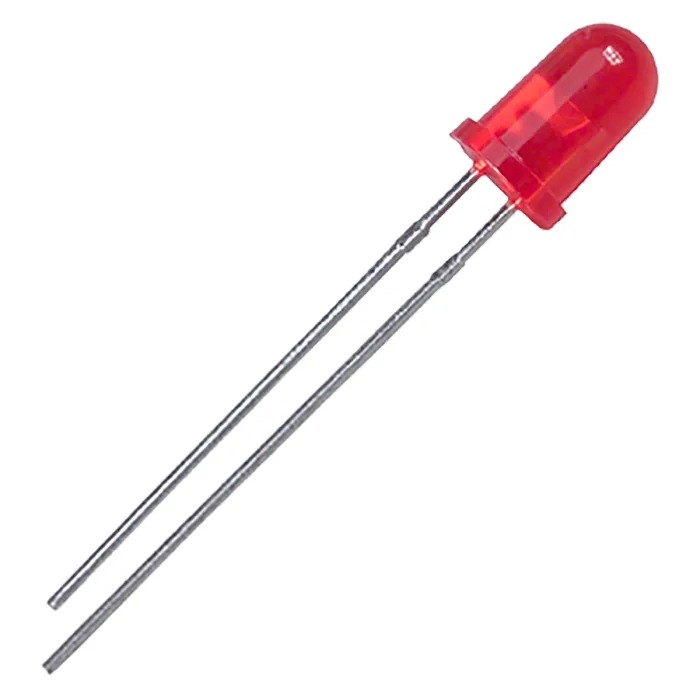
| Red LED | 1 | Indicates “Danger” zone |
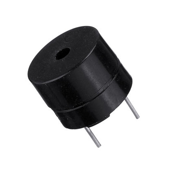
| Buzzer | 1 | Beeps as warning, faster when closer |
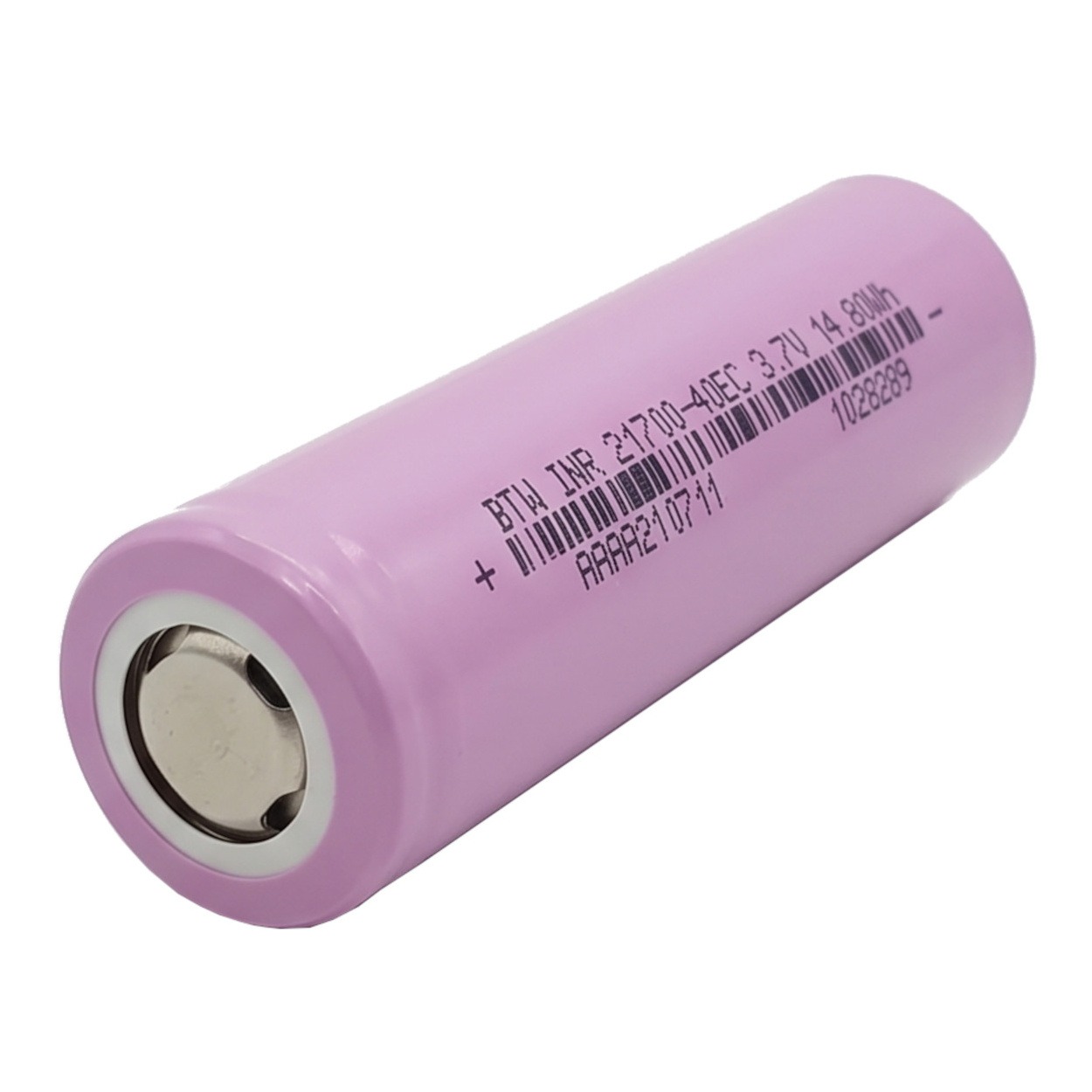
| 3.7V Li-ion Battery | 2 | Powers the circuit |
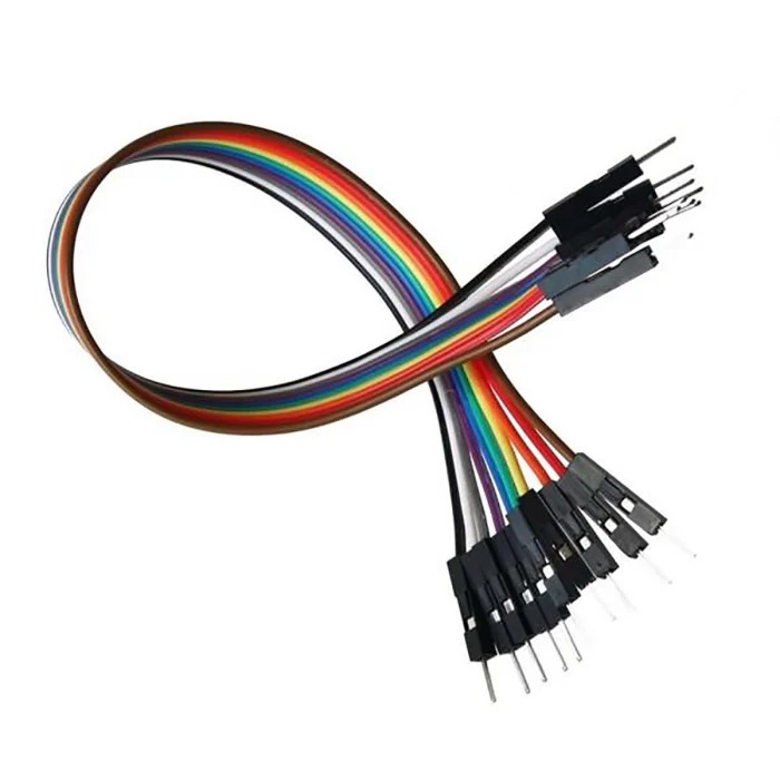
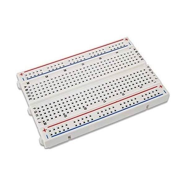
| Jumper wires & breadboard | As needed | Connections |
Arduino
HC-SR04 Ultrasonic Sensor
SG90 Servo Motor
SSD1306 OLED Display
Green LED
Yellow LED
Red LED
Buzzer
3.7V Li-ion Battery
Jumper Wires
Breadboard
I²C Address used in code: 0x3C
Open Arduino IDE → Sketch → Include Library → Manage Libraries, then search and install:
• Adafruit GFX Library
• Adafruit SSD1306
• Servo (usually pre-installed with Arduino IDE)
• Check the correct board and port are selected.
• Make sure no other program (like Serial Monitor) is holding the port open during upload.
• Try a different USB cable/port if the Arduino isn’t detected.
1. Setup: On power-up, the Arduino initializes the OLED, attaches the servo, and shows a “RADAR” start screen for 1.5 seconds.
2. Sweep: The servo moves in 2° steps from 0° to 180° and back, continuously, like a real radar dish.
3. Distance Measurement: At each angle, the Arduino sends a short ultrasonic pulse from the Trig pin, listens for the echo on the Echo pin, and converts the time taken into a distance in centimetres using distance = duration / 58.0.
4. Display Update: The OLED redraws the radar screen each cycle — range rings and a sweeping line show the current scan angle, a dot marks any detected object within 30 cm, and the angle, distance, and status are printed as text.
5. Warning System: Above 30 cm the green LED is on (Safe); between 10–30 cm the yellow LED is on with a slow beep (Warning); below 10 cm the red LED is on with a fast beep (Danger).
6. Serial Output: The current angle and distance are also printed to the Serial Monitor for debugging.
7. Loop: All of this repeats continuously, giving a live, constantly updating radar display.
Output indication using LED
Object detection using OLED
Scan the QR code below to download the full Arduino sketch for this project.
YABOT ACADEMY
Igniting the Passion for Robotics in Kids