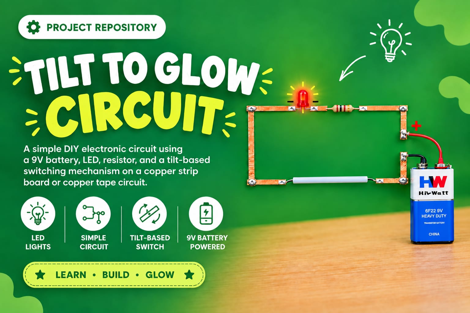
Design and build a simple LED circuit using a 9V battery, resistor, LED,
and a tilt-based switching mechanism on a copper strip board or copper tape circuit.
The LED lights up when the base is tilted at a specific angle.
Note: Please read the full instructions before making the product.
DIY Electronics Project
Beginner
To design and build a simple LED circuit using a 9V battery, resistor, LED, and a tilt-based switching mechanism on a copper strip board or copper tape circuit that lights up when the base is tilted at a specific angle.
This project demonstrates how an electrical circuit can be controlled using a physical tilt switch. The tilt motion completes the circuit, allowing the LED to glow and showing how sensors or switches can control current flow in simple systems.
| Material | Quantity |
|---|---|
| LED | 1 |
| 9V Battery | 1 |
| Battery Connector | 1 |
| Resistor – preferably 1kΩ | 1 |
| Copper Strip Board or Copper Tape | Small pieces |
| Speaker Wires | 2–3 pieces |
| Straw – acts as a simple tilt switch | 1 |
| Cardboard / Thermocol / Foam Board | 1 (A5 or A4 size) |
| Insulation Tape or Glue | As needed |
| White Paper | 1 sheet |
| Colors or Markers | For circuit layout and labeling |
★ The tilt mechanism acts as a manual switch for the power supply.
★ When the setup is tilted, a wire inside a straw rolls to one end and touches a copper path connected to the battery’s positive terminal.
★ This action completes the circuit by delivering power to the LED and resistor, causing the LED to light up.
★ This demonstrates how a position-based switch can control a circuit.
This demonstrates:
Follow the steps below carefully to assemble the Tilt to Glow Circuit.
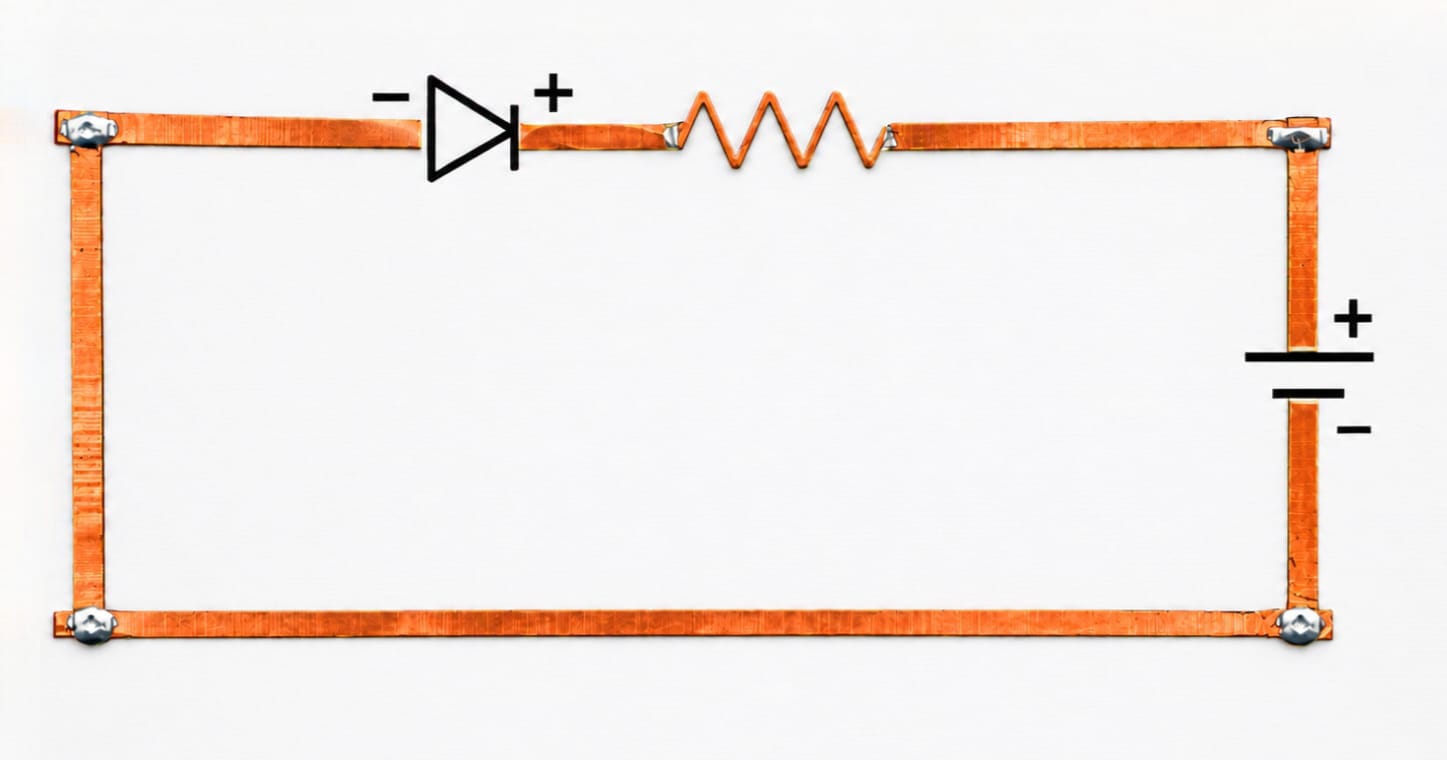
Step 1. Prepare the Base
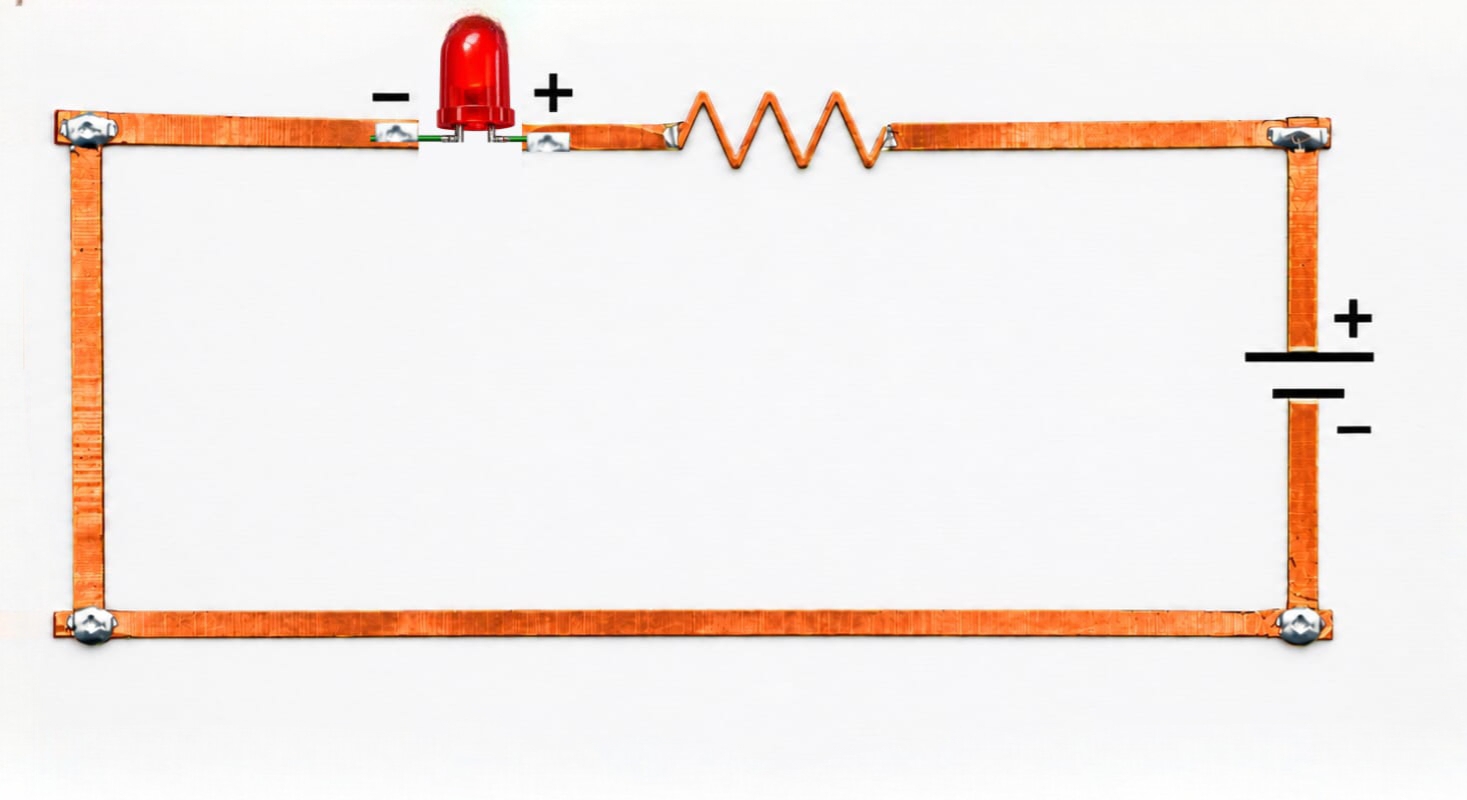
Step 2. Insert and Fix the LED
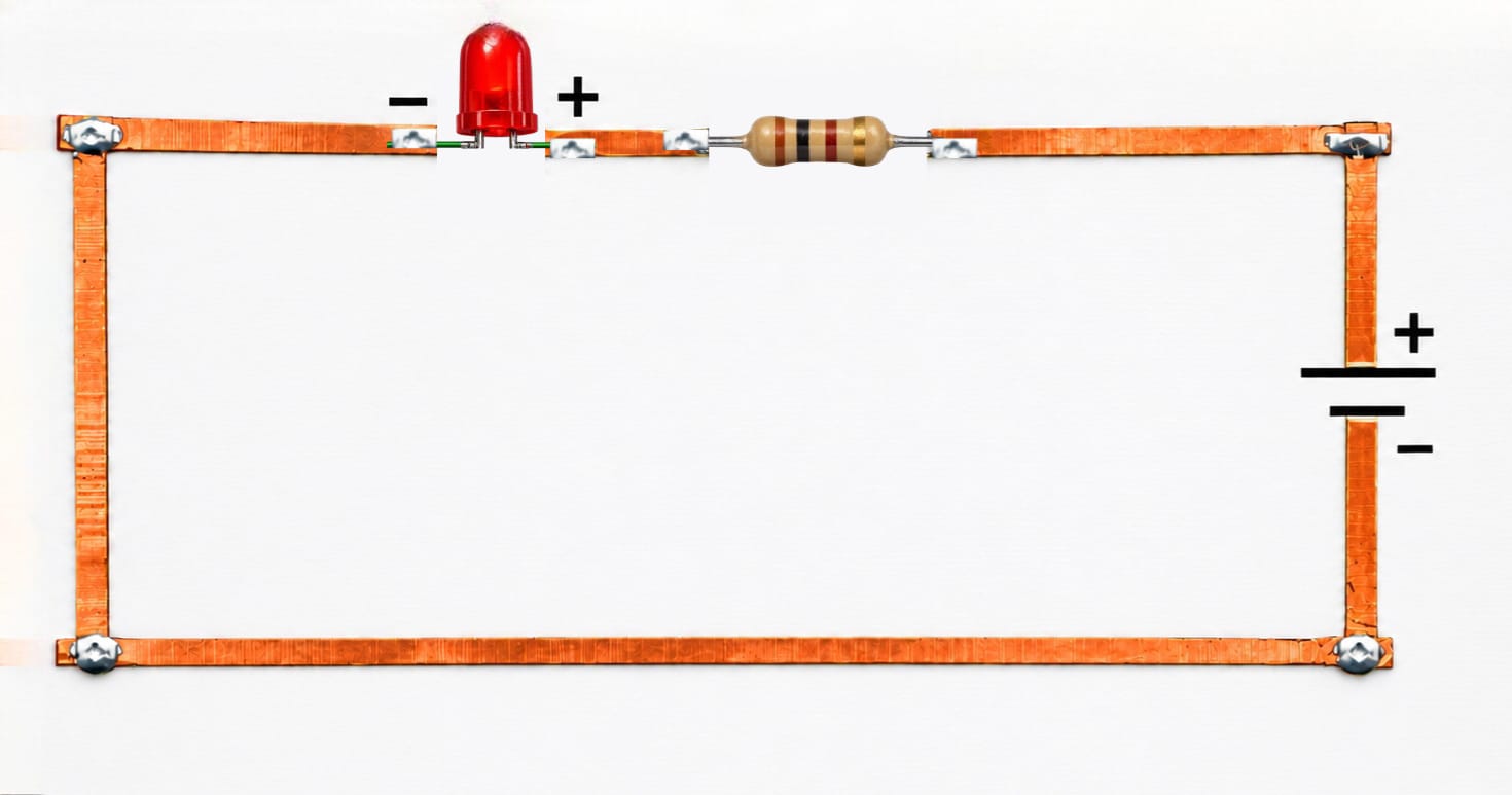
Step 3. Connect the Resistor
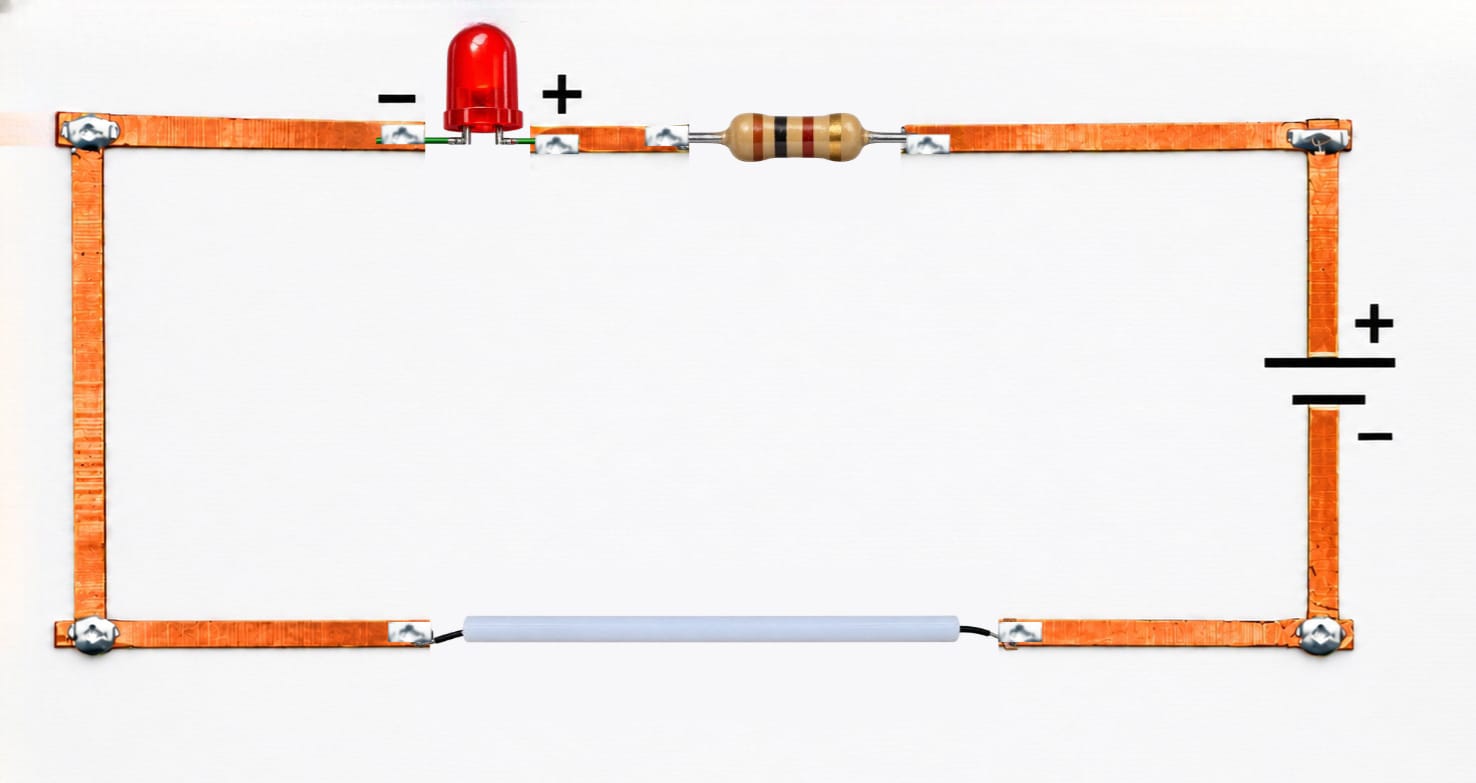
Step 4. Make the Tilt Switch – The Power Gate
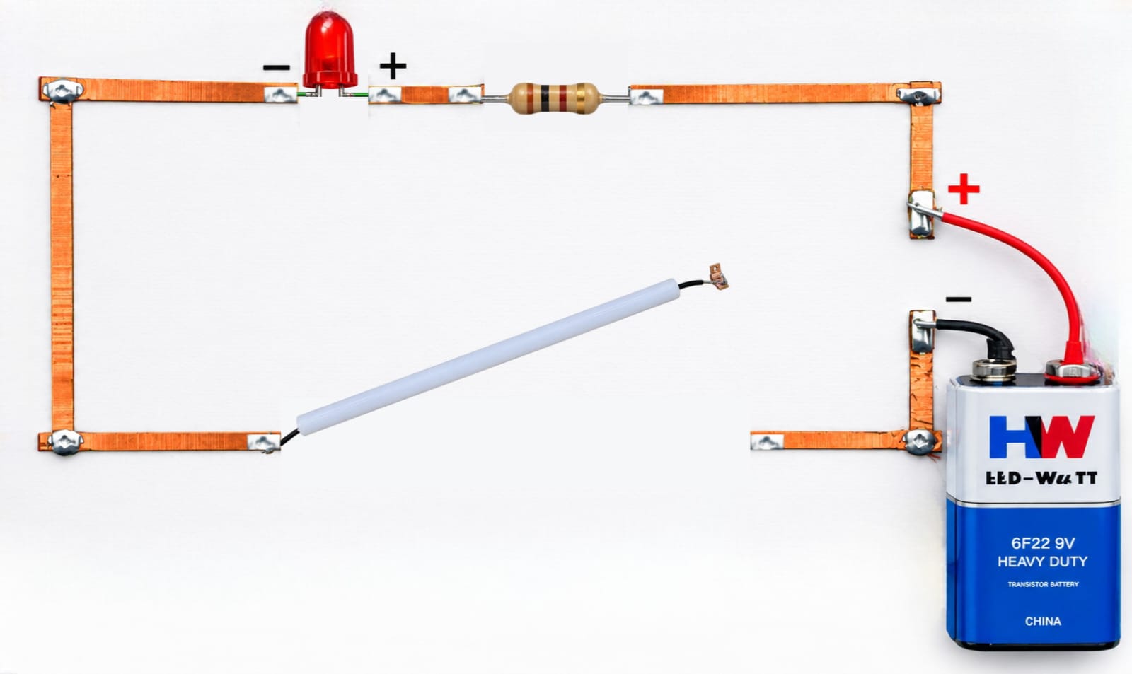
Step 5. Connect the Battery
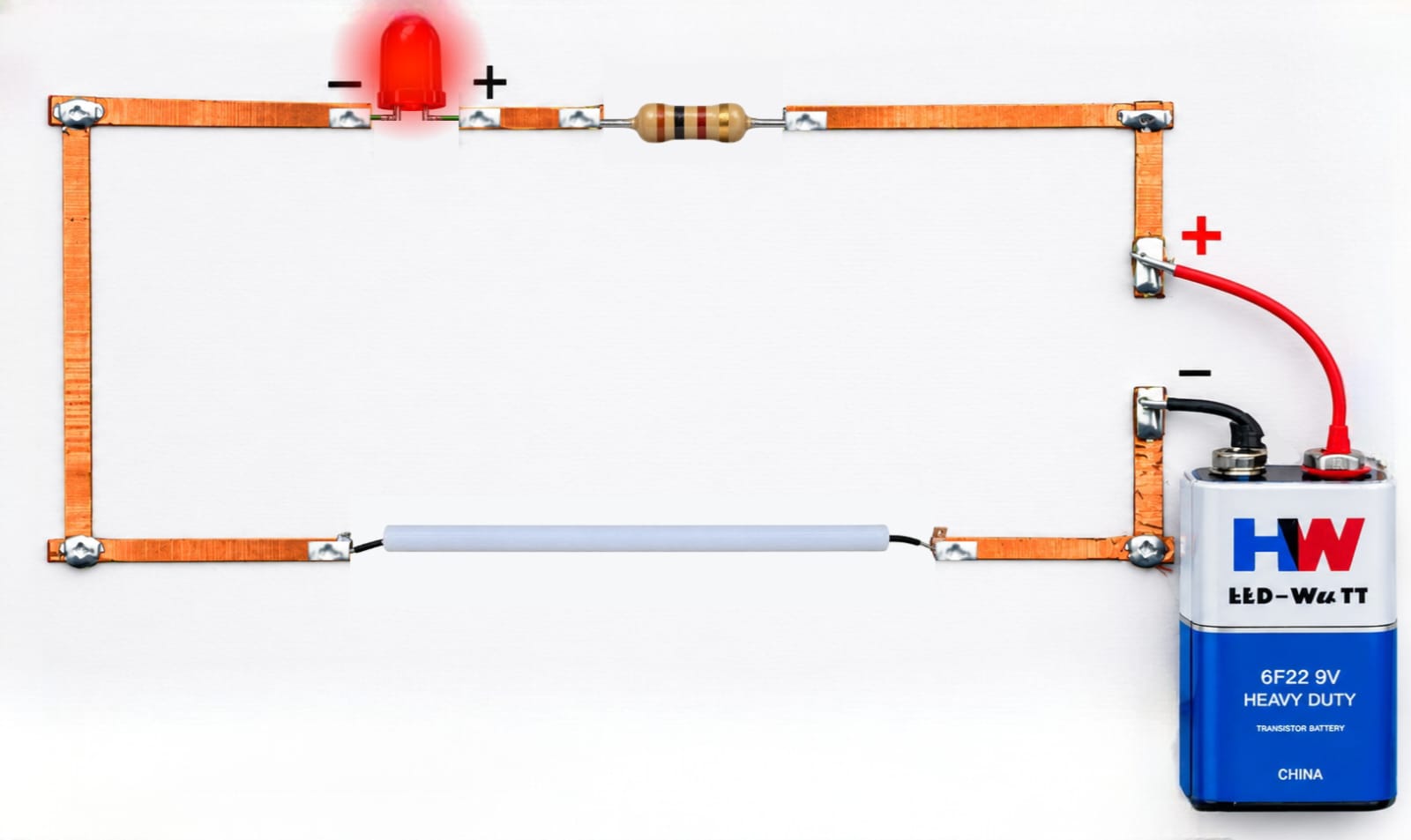
Step 6. Test the Tilt to Glow Circuit
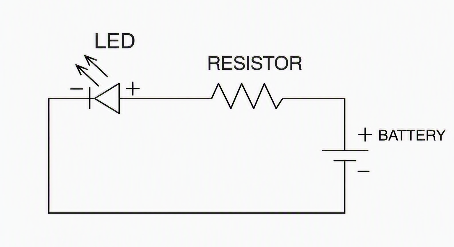
Figure 1. Circuit Diagram of the Tilt to Glow Circuit
When the base is tilted, the loose wire inside the straw rolls and makes contact, closing the circuit. This allows current to flow from the battery’s positive terminal, through the tilt switch, through the resistor, through the LED, and back to the battery’s negative terminal. The LED converts this electrical energy into light. When the tilt is reversed, the connection is broken, the circuit opens, and the LED turns off. This demonstrates a simple yet effective tilt-activated switch.
A fully functional Tilt to Glow LED Circuit was successfully built using copper strips and a handmade tilt switch. The LED lights up only when the system is tilted at a specific angle, confirming the creation of a position-sensitive electrical switch.
(i) Without tilting → Open Circuit
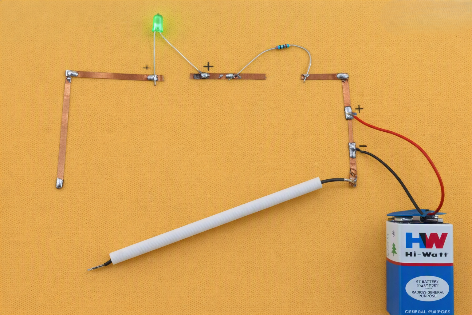
Sample Output – Without Tilting / Open Circuit
(ii) With tilting → Closed Circuit
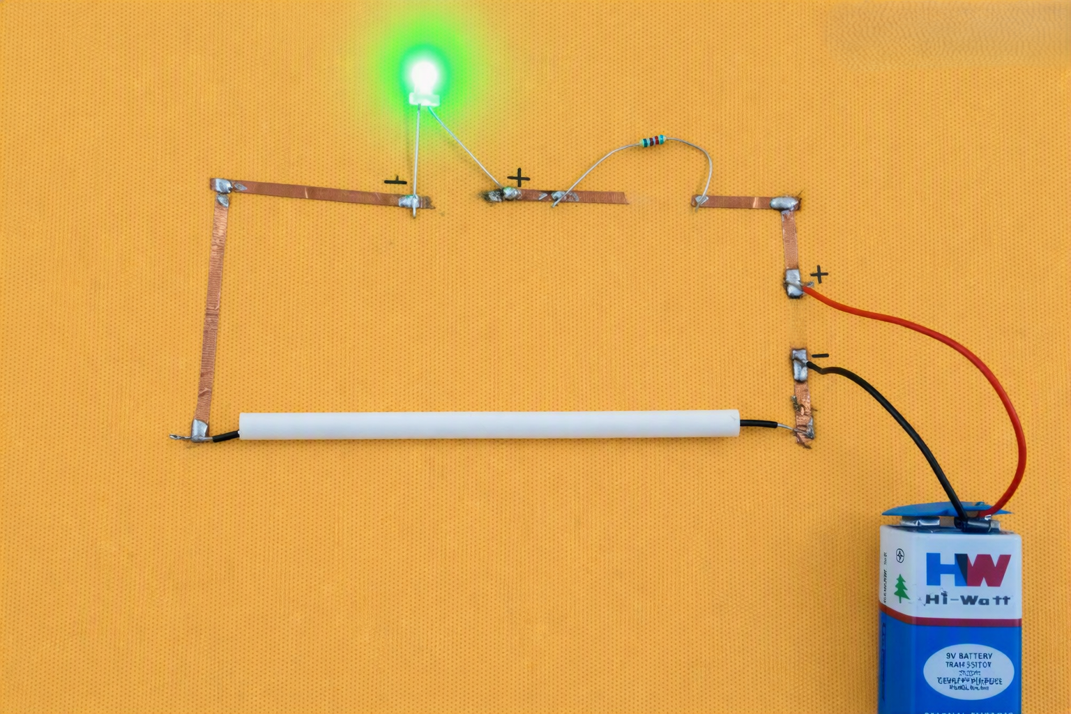
Sample Output – With Tilting / Closed Circuit