LED GREETING CARD – WITHOUT SWITCH

AIM:

To design and build a simple LED-based greeting card that lights up without using a traditional switch, using a coin battery, jumper wires, and safety pins as a conductive touch-based connection system.


OBJECTIVE:

This project demonstrates how an LED can be powered and controlled using direct physical connections instead of a conventional switch. It helps learners understand basic circuit connections, polarity, and the concept of conductivity in metals through a creative greeting card design.

MATERIALS PROVIDED:

1. A4 size thick paper (any color) – 1

2. LED (any color) – 1

3. Coin battery (3V) – 1

4. Female-to-female jumper wires – 2 (both ends cut)

5. Safety pins – 2

6. Double-sided tape – as needed

7. Transparent tape (Cellotape) – as needed

8. Colors or markers – for decoration and labeling

9. Scissors – 1

10. Glue (optional)

CIRCUIT DESIGN CONCEPT:

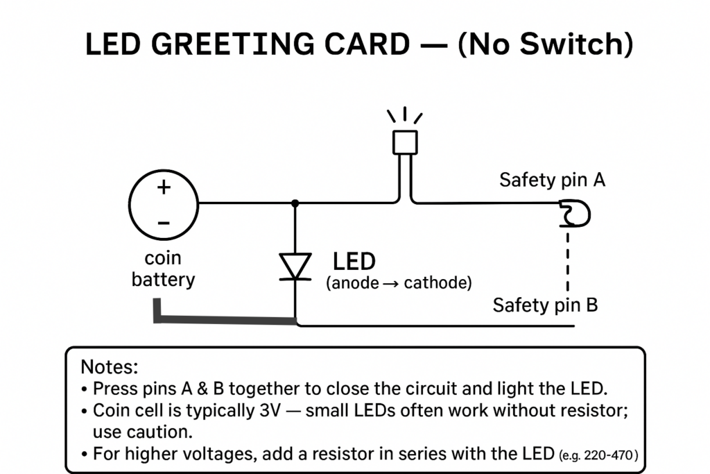
The LED greeting card works without a traditional switch by using two metallic safety pins that act as conductors. When the pins touch each other, they complete the circuit, allowing current to flow from the coin battery to the LED, causing it to glow. When the pins are separated, the circuit opens and the LED turns off. This setup illustrates how simple conductive materials can act as switch mechanisms in creative projects.

PROCEDURE:

STEP 1: PREPARE THE GREETING CARD BASE

  • Take an A4 size thick sheet of paper in any color of your choice.
  • Fold it neatly in half to form a card.
  • Open it, and use the right-hand side for the circuit connections.

ALTERNATIVES & TIPS:

  • You can decorate the front of the card with drawings, stickers, or a message before starting the circuit.
  • Use cardstock or chart paper for better support.

STEP 2: CONNECT THE LED

  • Identify the longer leg (anode +) and shorter leg (cathode –) of the LED.
  • Take two female-to-female jumper wires (both ends cut).
  • Connect one cut end of a wire to the LED’s positive leg (+).
  • Connect the other cut wire to the LED’s negative leg (–).
  • Secure both wire connections tightly with tape so they do not move.
  • Fix the LED carefully onto the paper so it stays upright.

 ALTERNATIVES & TIPS:

  • If the LED doesn’t stand well, use a small drop of glue to hold it in place.
  • Always double-check the LED polarity before connecting to the battery.
  • If the LED doesn’t stand well, use a small drop of glue to hold it in place.
  • Always double-check the LED polarity before connecting to the battery.

 STEP 3: CONNECT THE COIN BATTERY

  • Identify the positive side (usually marked with “+”) and negative side of the coin battery.
  • Place the jumper wire connected to the LED’s positive leg onto the positive side of the battery.
  • Place another small wire (from the LED’s negative side) onto the negative side of the battery.
  • Secure both connections tightly with tape.

ALTERNATIVES & TIPS:

  • You can use a small piece of double-sided tape or fold the tape edges to make a battery holder.
  • Ensure there’s no loose contact; otherwise, the LED won’t glow.

STEP 4: TEST THE CIRCUIT

  • Before assembling further, test the basic connection.
  • Touch the wire from the battery’s negative side to the wire connected to the LED’s negative side.
  • If the LED lights up, your basic circuit is working correctly.

TROUBLESHOOTING TIPS:

  • If the LED doesn’t glow, check polarity and ensure all tape connections are tight.
  • Replace the coin battery if it’s weak.

 STEP 5: CREATE THE SWITCHLESS MECHANISM

  • Take two safety pins.
  • Secure the thick end of the first safety pin to the tiny wire from the battery’s negative side using tape.
  • Secure the thick end of the second safety pin to the wire from the LED’s negative side.
  • Take a small piece of double-sided tape and place the first safety pin (connected to battery) on it — make sure the shorter pin end remains free.
  • Place the second safety pin (connected to LED) just above it on the same tape, creating a small gap between both pins.
  • This gap will allow the circuit to remain open until the pins are pressed together.
  • When you press the pins so that their metallic parts touch, the circuit closes, and the LED glows.

ALTERNATIVES & TIPS:

  • Other conductive materials (like paper clips, foil strips, or copper tape) can replace safety pins.
  • Keep the pins slightly apart so that the LED only lights when pressed.

STEP 6: CONCEAL & DECORATE THE CIRCUIT

  • Once your circuit works properly, cover it with a clean cut out sheet or designed card cover.
  • Use double-sided tape around the borders of the mechanism to fix the cover neatly.
  • Ensure the LED protrudes through a small hole or window for a glowing effect.
  • Now, design your greeting card creatively — add messages, drawings, or themes like “Happy Birthday” or “Thank You.”

ALTERNATIVES & TIPS:

  • You can shape the LED glow as part of the design (like a star, heart, or candle flame).
  • Use color markers or stickers for a personalized look.

CIRCUIT DIAGRAM:

WORKING PRINCIPLE:

When the two safety pins touch, they act as a conductor and complete the circuit path between the battery and the LED.

Current flows from the battery’s positive terminal → LED anode → LED cathode → safety pins → battery’s negative terminal. This flow of current lights up the LED. When the pins are separated, the circuit is open, and the LED turns off. Thus, the greeting card glows only when pressed, creating a fun and interactive design without using a physical switch.

REFERENCE VIDEO LINK:

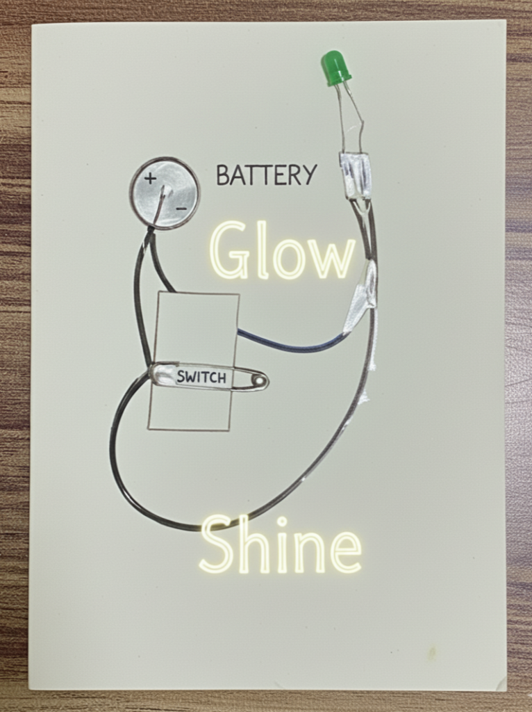
FINAL RESULT:

SAMPLE OUTPUT (CONNECTIONS):

(i) When not pressed – Open Circuit (LED OFF)

(ii) When pressed – Closed Circuit (LED ON)

FINAL OUTPUT:

ADDITIONAL NOTES:

SAFETY:

  • Avoid short-circuiting the coin battery.
  • Disconnect the LED wires when not in use to preserve battery life.
  • Handle safety pins carefully to prevent injury.

CREATIVITY EXTENSION:

  •   Use multiple LEDs for decorative light effects.
  •   Create themed cards (birthday, festival, or thank-you).
  •   Experiment with copper tape instead of safety pins for hidden circuits.
  •   Add a small paper press button instead of pins for a smoother user experience.

Leave A Comment

Your email address will not be published. Required fields are marked *